


 HME NEXEO | HDX™ Crew Communication Platform / User’s Guide
NEXEO | HDX™
Crew Communication Platform
User’s Guide
Chapter 1 - NEXEO | HDX™ Overview
Congratulations on your investment! You are now equipped with the best wireless system available
for your business needs. This system is designed for but not limited to Quick Service Restaurants
(QSRs) and Stores that utilize a drive-thru. It delivers a clear, easy, and efficient way of communicating
with customers and employees. The Base Station offers a user-friendly touchscreen that provides
you with an enhanced range of customizable communication options that will help optimize the efficiency
of your business.
Equipment
Your basic system includes:
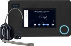
• Base Station: This is the control center for your entire
system. All peripheral devices and connected components
are controlled from here. Headsets are paired
here for use, and your system is also configured here.
The Base Station also provides feedback on the status
of system components such as headsets, speakers, and
batteries. (Fig. 1.1.)
• Headset: The headset allows you to communicate
with other employees and customers within a store or
drive-thru lane environment. (Fig. 1.2.)
• Remote Transceiver: This device facilitates wireless
communication between the headsets and the Base Station.
Up to four Remote Transceivers can be connected
to a Base Station (additional Transceivers extend range
to provide greater coverage in larger premises). (Fig.
1.3.)
• Battery Charger: This unit allows you to charge up to
four headset batteries at a time and also provides feedback
on the current condition of each battery docked.
Charger activity can be monitored via the Base Station
or the charger can be used independently as a standalone
charger. (Fig. 1.4.)
• Speaker/Microphone (not shown): These include external
speakers and microphones found in speaker posts
or menu board enclosures typically located in drive-thru
lanes. Speaker posts also contain a microphone which
may be a separate device or a combined speaker/microphone
assembly. These devices facilitate 2-way communication
between the store and customers at menu
boards, kiosks, and in drive-thru lanes. In-store ceiling speakers can also be connected to the Base Station.
The Home Screen
The interactive HOME screen provides you with a complete overview of your system at a glance.
Innovative smart features enhance ease of use while color-coded indicators provide a quick visual
status of a feature or component. Once your system is installed, it is initially configured by the installer
to your specifications. Fig. 1.5 shows your HOME screen. The small dots in the center of
the screen indicate the number of available screens, while the blue dot indicates the current screen
displayed. Click on a dot or drag/swipe the screen to the left or right to view the other screens. Fig.
1.5 shows you the status of all system components connected to the Base Station.
olor-coded indicators are used to give a quick visual status of a feature or component.
A green indicator means that the feature/component is online, active, and functioning properly.
In this example, the Speaker/Mic is connected and functional.
A red indicator means that the feature/component is offline, inactive, or not functioning properly.
In this example, there are no headsets detected; a headset needs to be turned on or paired
for this indicator to turn green.
A yellow indicator is a transitional state, such as when the Transceiver is scanning for available
channels. The indicator turns green once the Transceiver finds an available channel.
A gray indicator means that no AC70 Smart Battery Charger is detected. Note: This indicator
is gray instead of red because the AC70 charger doesn’t need to be connected to the Base
Station to be functional; it can function independently. Position the AC70 charger within 10 ft (3
m) of the Base Station for this indicator to turn green (the AC70 charger must also be powered
on)
Tap on a component or feature on the home screen to expand it for more details (see Fig. 1.6).
Fig. 1.6
Feature Description
Link: checks that the Post and Base Station are communicating
Loop Health: checks that the vehicle detection loop is functioning properly
Speaker/Mic: checks that the speaker mic for this lane is functioning properly
Traffic: shows how many conversations are happening now
In Use: shows how many headsets are currently in use
Status: provides a headset status, those functioning normally or not.
Status: This tells you whether the transceiver is online or not
Remote Transceiver: This the transceiver’s unique id/serial number
Details: This informs you if the transceiver is functioning properly or otherwise
Battery Status of Ports 1 - 4: Each port tile tells you the status of the battery docked in it,
whether it is charging, fully charged, dead or unauthorized. Tap on any of the port tiles to expand
for more details such as charging time, charge cycles, charging current, temperature, and
serial number.
Note: Battery charging status is also indicated by the LEDs on the AC70 Battery Charger. See
Table 1.2 for details
Alert: System alerts can be viewed here. Alert details include name, date, and time.
Network: This provides you with your LAN (Local Area Network) and HME CLOUD status.
Table 1.1
Tap here to choose an available language.
NEXEO | HDX ™
Tooltips also provide you with information. Tap on i to open.
The ACTIVITY Indicator at the bottom
of the HOME screen shows headsets in
use. The example here (in blue) indicates
headset activity; the Order Taker is communicating
with a drive-thru customer
(two-headed arrow).
Link: checks that the Post and Base Station are communicating
Loop Health: checks that the vehicle detection loop is functioning properly
Speaker/Mic: checks that the speaker mic for this lane is functioning properly
Traffic: shows how many conversations are happening now
In Use: shows how many headsets are currently in use
Status: provides a headset status, those functioning normally or not.
Status: This tells you whether the transceiver is online or not
Remote Transceiver: This the transceiver’s unique id/serial number
Details: This informs you if the transceiver is functioning properly or otherwise
Battery Status of Ports 1 - 4: Each port tile tells you the status of the battery docked in it,
whether it is charging, fully charged, dead or unauthorized. Tap on any of the port tiles to expand
for more details such as charging time, charge cycles, charging current, temperature, and
serial number.
Note: Battery charging status is also indicated by the LEDs on the AC70 Battery Charger. See
Table 1.2 for details
Alert: System alerts can be viewed here. Alert details include name, date, and time.
Network: This provides you with your LAN (Local Area Network) and HME CLOUD status.
Fig. 1.7 shows the HOME screen with the sidebar menu on the left. A four-digit PIN is required to
access most menu options (see “Permissions and Log in” on page 14 of this chapter). Each menu
option is covered by a chapter in this guide as assigned here in Fig. 1.7.
Connect the power adapter to the AC70 and plug the other end into a wall outlet. When positioned
within 10 feet (3 m) of the Base Station, the indicator on the HOME screen will change
from (gray) to (green), see Fig 1.8.
Note: The AC70 will still charge batteries outside of this range, but charging status cannot be
monitored via the Base Station HOME screen (the indicator remains gray when out of range).
2. Insert a battery into any charging port to begin charging (even new batteries need to be charged).
Batteries are keyed to only fit one way, and are easily docked with minimal effort. Do not force fit.
3. Tap the tile on the HOME screen to view charging status (if within range). If the AC70 is
out of range, then use the LEDs on the AC70 to monitor the charging status (see Table 1.2).
Fig. 1.9 shows that Ports 2 and 3 have docked batteries. The battery in Port 2 is charging while
the battery in Port 3 is fully charged. You can also press on a port tile for more details. For example,
when you tap on the Port 3 tile, another window opens below it and displays details about the
battery docked in it, see Fig. 1.10.
Headset (HS7000) Overview
The AIO HS7000 Headset (Fig. 1.11) is an all-in-one wireless headset. It uses one BAT70 lithium-ion
battery. Under normal use, the headset will operate for approximately eight hours on a single battery
charge and will alert you when the battery charge is low.
Lane 1 Green Green Tap to talk to lane 1. The Status LED flashes green while the Boom LED turns on solid
green (with audible single-tone confirmation). Tap again to stop (two-tone confirmation).
Voice Command: “lane 1” (to listen only) or “talk to lane 1,” or “change lane” if in lane 2
Lane 2 Red Red Tap to talk to lane 2. The Status LED flashes red while the Boom LED turns on solid red
(with an audible single-tone confirmation). Tap again to stop (with two-tone confirmation).
Voice Command: “lane 2” (to listen only) or “talk to lane 2,” or “change lane” if in lane 1
Volume
Up
Tap to increase volume (the headset beeps become louder as confirmation). Press and
hold to maximize volume to loudest. Voice Command: “volume up” or “volume #”
Volume
Down
Tap to decrease volume (the headset beeps become quieter as confirmation). Press and
hold to minimize volume to quietest. Voice Command: “volume down” or “volume #”
Group
Tap for group chat. Both Status and Boom LEDs flash quickly, alternating red & green.
(with an audible single-tone confirmation). Tap again to stop (with two-tone confirmation).
Action No Function. Reserved for future functionality.
Notes: Both the Status and Boom LEDs flash slowly, alternating colors when the headset needs to be paired. A yellow Status
LED indicates a low battery. The low battery Status LED is also accompanied by audio prompts.
Voice commands: See Table 1.4 for more details.
Push-to-Talk mode: Press and hold any audio button (L1, L2 or Group Chat) to use in this mode (there is an audible single-tone
confirmation). Release to cease communication and exit this mode (there is an audible two-tone confirmation).
Voice Commands
This option allows headset users to operate their headset using audible commands instead of having
to touch the headset keypad to do so. Voice commands must first be enabled on the base station in
order to use this option. See Voice Commands under System “Settings” on page 24.
The following table provides you with a list of available voice commands. All voice commands must
be preceded by the command “OKAY NEXEO” followed by the specific command prompt listed in
Table 1.4.
NOTE: Volume up and Volume down commands increase or decrease the volume one level at a time.
Instead of having to repeat volume up or down to get to a desired volume level, you can also
use a numerical value to jump to a desired level. The valid audible volume level range is 1 - 15,
with 1 being the quietest, and 15 being the loudest. 0 is mute. For example, if you are at volume
level 5 but need a much louder volume, you can say “Ok Nexeo volume 12” which will jump the
volume from level 5 to level 12.
Navigating the Screen
Almost every option or feature displayed on the UI has a small i icon next to it. This is a tooltip
(see Fig. 1.12). When you tap or hover over this icon, an information dialog opens, defining what this
option/feature is or does.
Fig. 1.12
Most screens have active areas which are editable; these may include the following:
Direct Access Fields: These are fields you can type directly into. When you tap in this field, a popup
keyboard also opens (see Fig. 1.13). This allows you to enter information using the touch screen
(without the need for a physical keyboard).
Fig. 1.13
Adjustment Counters: Some active areas such as time fields are edited by tapping on the field (see
Fig. 1.14). Tap on a number above or below the blue field to change. Continue doing so until the desired
number is in this field. The minute and second fields are controlled separately.
On/Off Switches: Tapping on an OFF/ON switch turns it on (if its current status is off, or off if its current
status is on). Fig. 1.15 shows two features, one in the OFF state, the other in the ON state).
Fig. 1.15
Drop-down and Pop-out Lists: The down-arrow in a field or next to the field indicates there are
more options available to choose from. The More icon (ellipsis icon: the three vertical blue dots in Fig.
1.16) also indicates there are more options to choose from. Tap on the arrow or More icon to open the
list and select from the available options.
Fig. 1.16
Sliders: Some adjustments, such as volume controls, are made using a slider bar. Touch the slider
knob and drag it to the right to increase the value or to the left to decrease the value. Or, you can use
the + or - sign on either end of the slider for single-step adjustments. The blue number next to the
slider knob indicates the current setting, while the minimum and maximum values are listed at the
start and end of the slider bar, respectively (see Fig. 1.17 ).
Getting Started with Pairing and Log In
Pairing
Before you can start using your system, you must first pair your headset with the Base Station. Pairing
links the headset to the Base Station, allowing it to recognize your headset and communicate with
it. Fig. 1.18 is the pairing screen on the Base Station Home screen, prompting you on how to pair
your headset. Even if this screen is not visible, the Base Station will sense when a headset is placed
next to the blue pairing ring and will begin pairing (see Fig. 1.19 ). Fig. 1.20 shows how the blue pairing
ring responds once it senses a headset within range. The solid blue pairing ring turns to a swirling
green ring indicating that pairing is in process. Pairing is complete and successful when the swirling
green becomes a solid green circle. Headset registration also happens automatically with the initial
pairing of a headset.
If your headset has a low battery, a battery level low alert ( ) is displayed prompting you to resolve
the situation before proceeding. Either charge the battery or replace it with a fully charged one.
NOTE: If pairing fails (indicated by a red swirling pairing ring), try again by holding the
headset steady, centered, and flush against the Headset Pairing Ring (headset
movement and distance from the Pairing Ring can cause pairing errors).
Pairing will also fail once the battery level drops to approximately 5% or below.
Once your headset is successfully paired, you are prompted to select a position (see Fig. 1.21). Tap
on a tile to select your position. This selection assigns you to a channel. If you are selecting DRIVE-THRU
(or DRIVE-THRU 1/DRIVE-THRU 2 for Y-Lane/Dual-Lane stores), you have the option of AUTO HANDSFREE
mode rather than having to connect with a new customer manually by tapping a headset button.
When you check this box located below the DRIVE-THRU tile (see Fig. 1.21), you are automatically
connected with a customer when they arrive at the order point. You are then automatically disconnected
when they leave the order point. The headset remains in this mode until the headset is powered
off and on again. This feature is only available for one headset per drive-thru lane. For example,
if a user selects AUTO HANDS-FREE mode when it is already in use with another user, this new user
will force the initial user out of this mode. This happens because this mode is only available for one
user per lane.
Once you Select Your Position, the prompt in Fig. 1.22 appears. Your headset is now ready to use.
14 © 2022 HM Electronics, Inc. All rights reserved.
Log In
A four-digit PIN is required to access the sidebar menu options such as CREW, DRIVE-THRU, MESSAGE
CENTER, and SYSTEM. The Store Manager receives this pin code upon installation. You can record it
here: ______
1. Tap LOG IN on the sidebar menu (Fig. 1.23). This opens a dialog box and prompts you for a PIN
(Fig. 1.24).
Fig. 1.23
Fig. 1.24
2. Tap the PIN field and enter your four-digit PIN using the pop-up keypad (Fig 1.25).
Fig. 1.25
3. Tap the button to accept (the keypad disappears).
4. Tap the button to log in. Click on any option to open that option screen.
NOTE: The following chapters assume that you have logged in to the Base Station.
© 2022 HM Electronics, Inc. All rights reserved. 15
2
CREW
Chapter 2 - Crew
Only Installers and Managers can access and edit the features
on this screen.
Fig. 2.1
What is this screen for? This screen allows you to set up crew profiles for those using the system.
1. Tap on the blue + New Crew Profile button to begin.
2. In the New Crew Profile window, enter details. See Fig. 2.2
NOTE: Fields with * are required fields. The Save button remains inactive until the required
fields are populated and then becomes active.
3. Tap the “Save” button to save the new profile. A green success banner confirms, see Fig. 2.3.
PERMISSIONS are active (ON) by default, click the toggle switch to disable (OFF).
Initiate 1-to-1 calls to Crew*: This option allows you to disable the ability of the crew member listed
to initiate a conversation with another crew member, however, another crew member with this
option enabled can initiate a conversation with the crew member who has this option disabled.
Send Messages to Crew*: This allows one crew member to leave a message for another crew
member, which is useful for when perhaps you need to correspond with another crew member
who is working a different shift or schedule.
* These options may not be initially available.
To add another crew member tap on the + New Crew Profile button again.
To Delete a profile, tap on the name of the profile you wish to delete and in the Crew Profile Detail
window, tap on Delete Profile (see Fig. 2.2), a prompt will follow asking are you sure. Tap the “Yes,
Delete” button to delete. A green success banner confirms.
Chapter 3 - Drive-Thru
Only Installers and Managers can access and edit the features
on this screen.
General
Fig. 2.1
What is this screen for? This screen provides you with some general settings you can adjust for
your drive-thru lane.
MUTE CHAT WHEN ORDER TAKING: Turning this ON mutes the Order Taker crew chat while communicating
with the drive-thru lane.
OUTSIDE ORDER TAKER: The default position is Off. Turning this On mutes the speaker post and vehicle
arrival tones when orders are taken by crew members outside.
For businesses that use an external on/off switch. Select “External” if you would prefer to control this
feature using an external on/off switch instead of controlling it here on the Base Station screen. (Contact
HME Sales/Support if you wish to include an external switch with your system.)
18 © 2022 HM Electronics, Inc. All rights reserved.
Volumes
Fig. 2.2
What is this screen for? This screen allows you to set volume levels for the speaker posts in your
drive-thru. Individual controls can be used to adjust specific audio features. Move the slider knob to
the left or right to decrease or increase the volume, respectively.
CUSTOMER VOICE: This controls the inbound volume for the customer’s voice from the speaker post
microphone at the drive-thru lane’s order point.
ORDER TAKER VOICE: This controls the outbound volume for the Order Taker’s voice going to the
speaker post at the drive-thru lane’s order point.
ARRIVAL TONES: This controls the volume of the arrival tones at the speaker post.
GREETER MESSAGE: This sets the volume for the Greeter Message if the Greeter Message is activated.
The Greeter Message is activated when enabled in the MESSAGE CENTER (see “Chapter 3 -
Drive-Thru” on page 17 for how to do this).
Chapter 4 - Message Center
Only Installers and Managers can access and edit the features
on this screen.
Messages
Fig. 3.1
What is this screen for? This is the message center where all your messages are available in one
location and can be enabled/disabled. Messages found here can be prerecorded messages or custom
messages you create (see “Audio Files” on page 22). It allows you to set conditions for audio
files and how they are used. Tap the blue ellipsis icon to the right of the “Status” column and select
from the drop-down list to view or edit details.
All Messages:
Tap on All Messages to view the available messages in the drop-down list. Choose a message type
from the list. This narrows the onscreen list to the specific message type chosen. Enabled messages
are indicated using white text, while disabled messages are grayed out. The Status column at the
end of the row also indicates whether enabled or disabled. To enable a disabled message, tap on the
More icon at the end of the row, and select “Enable” from the drop-down list.
New Message:
1. Tap on the button and select a message type. This opens a Create New Message
screen which walks you through setting up a message.
2. TYPE: Choose a message type from the available options. You can also set a message delay
here. The default is OFF. Tap switch to turn ON. The DELAY time field appears. Tap on the field
and use the MM:SS counter to select a time. Tap the Set button to save. Tap Next to move on.
3. AUDIO: Select an Audio file from the available list. Tap Next to move on.
4. SCHEDULE: Select a Schedule from the available list. Tap Next to move on.
5. DESTINATION: Select a Position or Destination from the available options (more than one option,
or even all options can be chosen, tap on each one to select). Tap Next to move on.
6. NAME: Name your message type and provide a description of it here. Tap Save & Complete to
finalize and exit.
7. Back at the Message Center screen, find your New Message on the list and enable it to activate it
(see previous All Messages section).
Note: The Next button is active when blue allowing you to advance to the next screen. If the Next
button is gray, it’s deactivated and thus requires a field to be populated or an option selected before
it turns blue, thereby allowing you to move on to the next screen.
Bulk Edit: Use this when you want to perform the same action on more than one file. When you tap
the button, a checkbox appears to the left of the NAME column. Check all boxes of the files
you wish to edit. Then, select from the “Bulk Options” drop-down list to perform the same action to
all the files checked. A prompt appears requesting you to confirm or decline your change. Tap Yes to
proceed with the change.
© 2022 HM Electronics, Inc. All rights reserved. 21
4
MESSAGE CENTER
Schedule
Fig. 3.2
What is this screen for? This screen allows you to put together a schedule of features you have set
along with a status of the feature, which can be adjusted here.
New Schedule: Tap on the button to create a new schedule. Follow the prompts and fill
in the appropriate fields. Tap “Save,” and the new schedule will appear under the NAME column (you
may need to scroll through the displayed entries to find it).
To filter the schedules shown under the NAME column, tap on the down-arrow next to “All Schedules”
and choose an option from the drop-down list. Tap the blue ellipsis icon to the right of the Status column
and select from the drop-down list to view, edit, or change the status of the schedule in that row.
Example: If there is an existing file not currently used and you wish to use it.
1. Tap on the down-arrow next to “All Schedules” and choose “Not Used” from the drop-down list. All
unused files are now filtered and displayed in the table.
2. Tap on the blue ellipsis icon in the row of the unused file you now wish to use and select “Enable”
from the pop-out list. The “Status” column for that schedule is updated to “Enabled,” and the file is
now active.
Bulk Edit: Use this when you want to perform the same action on more than one file. When you tap
the button, a checkbox appears to the left of the NAME column. Check all boxes of the files
you wish to edit. Then, select from the “Bulk Options” drop-down list to perform the same action to
all the files checked. A prompt appears requesting you to confirm or decline your change. Tap Yes to
proceed with the change.
Audio Files
Fig. 3.3
What is this screen for? This screen provides a directory of prerecorded audio sounds but also
allows you to import or record custom messages for use depending on your needs. The navy ribbon
across the screen tells you how many total audio files there are and the recording time remaining if
you wish to import more audio files or record custom messages.
All Audio Files: This column is where all the Audio Files reside. You can filter audio files by tapping
on the down-arrow next to it and selecting from the drop-down list. Tap the blue ellipsis icon for an
audio file entry to the right of the “Usage” column and select from the drop-down list to view or edit
details.
Record or Import: This button is either a Record or an Import button depending on whether you are
at the Base Station in person or connected to it remotely. To record a message if you are at the Base
Station, tap on the Record button, and follow the onscreen prompts first to pair a headset and then
record a message.
If you are connected remotely, the Record button is replaced with an Import button. Custom Audio
Files can be imported here. Tap on the button, and follow the onscreen prompts.
Once the audio file is recorded or imported, it is now available for use under Audio Files in the message
center.
NOTE: The only file format supported is .wav, and the file must be less than 15 seconds
in duration. Only one file at a time can be dragged and dropped.
Bulk Edit: Use this when you want to perform the same action on more than one file. When you tap
the button, a checkbox appears to the left of the NAME column. Check all boxes of the files
you wish to edit. Then, select from the Bulk Options drop-down list to perform the same action to all
the files checked. A prompt appears requesting you to confirm or decline your change. Tap Yes to
proceed with the change.
© 2022 HM Electronics, Inc. All rights reserved. 23
4
MESSAGE CENTER
Ceilings Speakers
Fig. 3.4
What is this screen for? This is where you can adjust volume levels for the ceiling speakers. Individual
controls can be used to adjust specific audio features. Move the slider knob to the left or right to
decrease or increase the volume, respectively.
CUSTOMER VOICE: This controls the inbound volume for the customer’s voice from the speaker post
microphone at the drive-thru lane’s order point.
ORDER TAKER VOICE: This controls the outbound volume for the Order Taker’s voice going to the
speaker post at the drive-thru lane’s order point.
ARRIVAL TONES: This controls the volume of the arrival tones at that speaker post.
MESSAGES: This sets the volume for all enabled messages. Messages are enabled in the
STORE>MESSAGES screen. Messages include greeters, alerts, and reminders.
CREW CHAT: This controls the crew chat volume.
Chapter 5 - System
Only Installers and Managers can access and edit the features
on this screen.
Settings
Fig. 4.1
What is this screen for? This screen gives you an overview of the entire system and is primarily
used by the installer and technical support for maintenance and updates. Tap on the tab to open the
drop-down list and select the option you wish to view. The Settings drop-down list enables you to see
and edit component setups and system configurations. Many of these options are performed during
the initial installation using the Installation Wizard. Options in this drop-down list are defined below.
Store Details: Store name, number, and address are recorded here.
Date & Time: Date and time formats are selected here, including time zone.
TIME SETTINGS: Gives you the choice of Auto or Manual setup. Choosing Auto will cause the Time
Server fields to populate automatically. The four fields below this option are Internet Time Servers
for Network Time Protocol (NTP). NTP is a protocol used to synchronize computer clocks across
multiple systems. It supports synchronization over local area networks and the internet. The Time
Setting option allows for up to four servers to be used.
© 2022 HM Electronics, Inc. All rights reserved. 25
5
SYSTEM
Store Hours: Open and Close times are recorded here. Click in the time field and use the adjustment
counter to set.
HME CLOUD: When set to ON, this screen shows your HME CLOUD connection details. While the
Base Station can function without a registered account, customers are advised to register in order to
get the most out of their system and receive updates.
Lane Setup: This refers to the layout of your physical drive-thru area.
Single: a store with one drive-thru lane.
Dual: a store with two separate drive-thru lanes and ordering points
Tandem: a store with two ordering points (one after the other) but only utilizing a single lane.
Lane Settings: The Base Station has several advanced audio processing features designed to improve
the quality of communication with the customer at the menu. This is screen allows you to manually
adjust these audio features, enhance fidelity, and reduce the effects of noise interference. Scroll
down the screen to access all these features.
Auto Volume Control (AVC): When on, AVC automatically reduces the volume level coming from
the outside speaker during quiet times, such as in the early morning or late at night. AVC monitors
the ambient sound level outside and adjusts the speaker’s volume level. If the ambient outside
sound level increases, AVC stops adjusting and returns volume to its original level.
Voice-Activated Attenuation (VAA): During the course of a conversation, when the Order Taker
is speaking to the customer, the customer’s volume is reduced to help reduce loud noises or echo
from the Order Taker’s microphone. The VAA option assures that as you speak, the sound from
outside is reduced. This switch needs to be turned ON to adjust the following Sensitivity and Attenuation
sliders (i.e., both sliders are disabled when this switch is OFF).
Inbound Noise Cancellation: This greatly enhances the Order Taker experience by virtually
eliminating all unwanted outside noise (such as a car engine) that may normally be picked up by
a microphone. Inbound Noise Cancel distinguishes human voice from ambient noise and filters
the audio, making the customer’s voice much more audible. Other outside sounds such as planes
flying over, sprinklers, or street noise are also filtered.
Outbound Noise Cancellation: When on, ClearSound virtually eliminates all in-store noise
from being heard through the outside speaker. A quick-service restaurant can produce unwanted
sounds caused by kitchen equipment and appliances necessary in the preparation of food. These
sounds can sometimes be picked up by the headset’s microphone and potentially heard by the
customer. Outbound Noise Cancel distinguishes human voice from in-store noise, filtering the
audio so that only the Order Taker’s voice is heard loud and clear by the customer.
Ext. Speaker: If an external speaker is connected and functioning properly, you can enable it
here, otherwise leave this switch in the OFF position.
26 © 2022 HM Electronics, Inc. All rights reserved.
Network: This provides you with protocol information concerning your network connection.
DHCP: Dynamic Host Configuration Protocol allows a network administrator to
supervise and distribute IP addresses from a central point. When the DHCP switch is ON, the
system automatically populates the required fields.
IP ADDRESS: Internet Protocol Address. A unique computer address that some electronic devices
(such as computers or routers) use to identify and communicate with each other on a computer
network.
SUBNET: Splits the network into a series of subgroups or subnets to speed up the delivery of
data by the routers.
GATEWAY: A device (usually a router) that connects one or more computers on a network to other
networks.
DNS: Domain Name Server is a directory of domain names with translated Internet Protocol
(IP) addresses. When the DNS switch is ON, the system automatically populates the required
fields.
MAC Address: This is a unique identifier assigned to your system for use as a network address in
communications within a network segment.
Voice Commands: When this option is enabled, it allows headset users to operate their headset
using audible commands instead of having to touch the headset keypad to do so. Toggle the switch to
ON to enable. Enabling this option requires a system restart, follow the onscreen prompt. The available
voice commands are explained under headsets, see “Voice Commands” on page 8.
Remote Transceiver: This provides feedback on which channels are being used. Channel A is the
primary channel, with channel B being the secondary channel. You can use the More icon at the end
of the Remote Transceiver row to scan, or reset the transceiver.
Snapshots: This provides you with a backup of data settings or custom configurations like your last
software update, your most recent installer, or factory activity. Such configuration snapshots can help
the installer/manager restore a system to a previous custom setup if the configuration is somehow
lost or reset.
User Snapshot: If after the installer configures the system, the manager decides to change some
of the system settings, they can create a user backup of their changes. After making the changes
and saving them, tap the Create User Snapshot button and enter a name. A Success prompt follows,
and the name of the backup file now appears under User Snapshot>NAME on the screen.
Tap the More icon at the end of the row to Edit, Restore, or Delete. The Restore option is the one
you would use to apply your settings if they were somehow lost, changed, or corrupted.
Detectors: This allows you to adjust your detectors for a given lane.
Detection: When Normal is selected, it refers to the standard mode of operation for detection.
When a vehicle arrives at a detection point in a lane, a vehicle alert tone is heard in headsets,
followed by inbound audio from the outside speaker.
When Override is pressed, the microphone at the menu is constantly on, and no arrival tones are
issued when a vehicle arrives at the detection point.
Detection Sensitivity: Set to a low value if you are having problems with ghost cars. Ghost
cars are detection anomalies that occur when a vehicle is detected at one detection point but not
detected at another. However, a lower detection threshold corresponds to slower detection at the
risk of small fluctuations, resulting in missed detections.
Detection Delay: This delays detection until the vehicle is fully detected on a loop. Increase the
value to increase the delay.
Release Sensitivity: This feature correlates to how quickly the vehicle detector circuit signals a
vehicle departure. It is recommended that this feature is set to as low as practical.
Set to a low value if multiple detections or dropouts frequently occur (dropouts are when a vehicle
is present at the detection point but not detected).
Set to a higher value to compensate for improperly positioned loops where run-ons occur (run-ons
are when a vehicle that has departed from a detection point but is still sensed as being present).
Check first for dropouts or run-ons and then set accordingly for the optimal operation.
Auto Reset Timeout: When set to “None,” vehicle detection never resets. To reset vehicle detection,
select 10 Minutes or 20 Minutes, and vehicle detection will automatically reset at the corresponding
time selected.
Diagnostic Mode: Under normal operation, leave this switch OFF. This is a troubleshooting
feature. Turning it ON suspends actual vehicle detection but simulates a vehicle arrival every 10
seconds.
Log Frequency: Select how often you want drive-thru events logged on a daily or weekly basis.
28 © 2022 HM Electronics, Inc. All rights reserved.
Troubleshooting
Fig. 4.2
What is this screen for? This screen provides you with system and component information that can
help you troubleshoot when issues arise. Tap on the tab to open the drop-down list and select the
option you wish to view.
Base Station: This gives you a profile of your Base Station,
including serial number and firmware version. You can also restart
the Base Station from here without having to disconnect and
reconnect power. Press the Restart Base Station button, and this
prompt appears suggesting to do this after service hours since the
system may take several minutes to reboot.
Headsets: This lists all headsets connected to or disconnected
from the Base Station. Click on the More icon at the end of the row
and select View Details to see additional details for any listed
headset.
Speaker/Mic Posts: This gives you a profile of your Speaker/Mic,
including serial number and firmware version. You can also restart
the Speaker/Mic from here without having to disconnect and reconnect
power. Press the Restart Speaker/Mic Post button, and a
prompt appears suggesting to do this after service hours since the
system may take several minutes to reboot.
© 2022 HM Electronics, Inc. All rights reserved. 29
5
SYSTEM
Updates
Fig. 4.3
What is this screen for? This screen provides you with system updates for firmware versions, etc.,
regarding your individual system components (i.e., the Base Station, Remote Transceivers, and
Speaker/Mic Posts). Tap on the tab to open the drop-down list and select the option you wish to view.
If a new version of firmware is available, it will be listed here. The system will notify you when a new
version becomes available. See “Firmware Updates” on page 33.
Snapshots: This provides you with a backup of previous updates.
30 © 2022 HM Electronics, Inc. All rights reserved.
Chapter 6 - help
Fig. 5.1
What is this screen for? If you have questions concerning your system, you may find the answer by
scanning this QR code with a smartphone camera. This lands you on the User Manual’s page of HME
Support. NEXEO guides are located under NEXEO | HDX and can also be accessed by going to:
https://www.hme.com/qsr/drive-thru-user-manuals/
Also, visit the HME Training Portal by scanning this QR Code:
or going to: https://www.hme.com/training
HME Technical Support: If the help provided in this section is not sufficient, please contact our Technical
Support team at support@hme.com or call us at 1-800-848-4468. As a valued customer, we are
here to help you have the best experience with your product; your success is our success!
Troubleshooting
Problem Solution
The Base Station is off (blank
screen)
The Base Station does not have a power on/off button; it turns on automatically
once it is plugged into a live wall outlet.
Verify the power adapter is plugged into a live wall outlet.
Verify the power cable is properly terminated to J1 on the Base Station
PCBA and that there is power from the power adapter to this end of the
cable (illuminated LEDs on the PCBA indicate there is power to the base
station).
The Base Station is on but not
responsive to certain actions
The entire HOME screen is not
responsive to touch
Log in to the base station, go to SYSTEM, click on the troubleshooting tab,
select from the menu and try restarting the component that is not responsive.
Restarts can take several minutes to complete.
Try a hard reset by unplugging the power cord from the wall outlet. Wait a
few seconds and then reconnect power. Reboots can take several minutes
to complete.
The headset does not power on Verify the BAT70 battery is fully charged and not dead (verify charge status
using the AC70)
Verify the BAT70 battery is inserted correctly and properly docked (you
should hear an audible click when it is properly inserted and securely
seated).
Verify the Power button depresses when pressed.
Verify the battery contacts in the headset battery holder and on the battery
are clean and free of debris.
Verify the battery is the correct type (only HME BAT70 batteries are valid,
the battery is labeled on the back),
The headset does not pair Verify the headset has a sufficiently charged battery and that the headset is
powered on (the headset status LED illuminates).
Hold the headset steady, centered, flush against the headset pairing ring.
Movement and proximity can cause pairing failures.
The headset has no sound Verify the headset is on and the headset is paired.
Verify the headset is within range of the transceiver
Press and hold the volume up button on the headset keypad. An audible
beep becomes louder as volume increases.
Headset communication is choppy
or drops off
Headsets have an effective range. Move the headset to within range of the
transceiver. Also, verify headset has a charged battery.
Large objects can also disrupt signal propagation. Try moving to a different
location or within line of sight of the transceiver.
Headset battery will not charge Verify the charger is plugged in and on.
Verify the battery is the correct type (BAT70).
Verify the battery is docked correctly in the port (the battery is keyed, so
it can only be inserted one way. It should not be forced into the charging
port).
Verify the battery and charger contacts are clean and free from debris,
contaminants, or obstructions.
Verify the battery is not dead. Batteries have a lifespan. They will eventually
die and will need to be replaced. The Base Station monitors battery
charge cycles and informs you when to replace a battery.
Additional Troubleshooting
If your system malfunctions, a red indicator on the HOME screen will alert you to where the problem
is (see color-code definitions below). If it cannot be fixed via the HOME screen, try resetting the
system component in question via the Base Station. For example, if the problem is the Speaker/Mic
Posts:
1. Select SYSTEM from the sidebar menu.
2. Log in to the system.
3. Select the TROUBLESHOOTING tab.
4. Choose Speaker/Mic Posts from the drop-down list.
5. Tap on the Restart Speaker/Mic Post button and follow the prompts to reset.
Or, try resetting the system:
1. Select SYSTEM from the sidebar menu.
2. Log in to the system.
3. Select the TROUBLESHOOTING tab.
4. Choose Base Station from the drop-down list.
5. Tap on the Restart Base Station button and follow the prompts to reset.
Electrical Power Outage: If your system fails to function properly after an electrical power outage,
power the system off by unplugging the AC power adapter from their electrical outlets. Wait a few
seconds, then plug them back in and power the system back on.
A red indicator like this one doesn’t always indicate a failure. It may indicates that the feature/
component is offline, inactive or possibly something else requiring corrective action. In
this example there are no headsets detected, a headset needs to be turned on and paired
for this marker to turn green. Tapping on the indicator will also reveal more details.
A red indicator like this one indicates a critical system failure, and requires immediate
attention. In this example the Transceiver has failed, which might be caused by a disconnected
or failed Ethernet cable or a loss of power. The system cannot function in this
condition until the failure is resolved.
A yellow indicator indicates an intermediate or transitional state such as scanning or an
alert. When the Base Station is turned on, reset, or receives an upgrade, the transceiver
indicator initially turns yellow as it scans the area for available channels before turning
green. This can take a few minutes.
A gray indicator like this one indicates that no AC70 Smart Battery Charger is sensed.
Plug in the AC70 and position it within 10 feet (3 m) of the Base Station for it to turn green.
Note: this marker is not red because the AC70 can function independently and does not
require a Base Station connection to be functional.
A red exclamation mark like this indicates a new firmware update is available.
If you cannot resolve problems with the information presented here, please contact HME Technical
Support at 1-800-848-4468.
A red banner like this is a prompt requiring attention. This banner contains the path to the feature or
field requiring attention. In this example, you are asked to go to the SETTINGS tab of the SYSTEMS
screen. “Lane Settings” is found in the SETTINGS drop-down list. Once there, you will notice that the
SPEAKER SELECTION field prompts you to “Select One.” For a single-lane, there is only one entry to
chose from, so select this entry. The Save button appears, click Save, and the speaker/Mic post is
now assigned to the lane. The red banner on the Home page disappears.
Firmware Updates
Red Exclamation Marks like the one next to the SYSTEM icon in Fig. 5.2 indicate that a feature or
component requires attention, such as a firmware update.
Fig. 5.2
1. Log in (see “Log In” on page 14) to proceed to the SYSTEM screen. The Red Exclamation Mark is
now also visible next to the UPDATES tab.
2. Tap on the UPDATES tab. In this example, the Base Station option requires attention. See Fig. 5.3.
Fig. 5.3
3. Select Base Station from the drop-down list
4. Tap the blue Update button that appears on the right. See Fig. 5.4.
5. The update begins and provides a progress status. Once the update is completed, the red exclamation
mark disappears
NOTE: Updates can take several minutes to load and should be performed after hours
to avoid service disruptions during business hours.
Glossary of Terms
Attenuation: Attenuation is a telecommunications term that refers to a reduction in signal strength
commonly occurring while transmitting analog or digital signals over long distances. Attenuation is
historically measured in dB, but it can also be measured in terms of voltage.
AOT (Automated Order Taking): Is a store-level voice AI feature that uses a bot to take customer
orders in the drive-thru so that staff are available to perform other roles in the restaurant.
Base Station: This is the central control unit for your system. The Base Station interfaces with all
system components, including the Cloud. System features are configured and controlled here; headsets
are also paired here.
ClearSound: This is a patented digital processing technology used to remove background noise from
audio transmissions.
CSV: Comma-Separated Value is a file containing values separated by a delimiter and formatted as a
database table.
DHCP: Dynamic Host Configuration Protocol is a network management protocol used on UDP/IP networks.
A DHCP server dynamically assigns an IP address and other configuration parameters to each
device on a network so they can communicate with other IP networks.
Dropout: This is the term used when a vehicle is present at a detection point but not detected by the
system.
Ellipsis/More icon: This icon is represented by three vertical blue dots and indicates there are additional
options available when tapped.
Gateway: A device (usually a router) that connects one or more computers on a network to other
networks.
Ghost Car/Vehicle: This is the term used when there are detection anomalies that occur when a vehicle
is detected at one detection point but not detected at another. There are a few reasons why this
can occur; for example, a vehicle drives over a detection point and then leaves the lane before reaching
the next detection point or vice versa. Another example is if vehicles are too close together but are
detected as one vehicle. Or if a vehicle moves too quickly across one of several detection points to be
detected.
Headset: This is the device worn by your crew/staff and used for 2-way communication between
employees and customers. It consists of an earpiece with button controls and a wrap-around microphone.
The system uses two headset models: AIO (All-In-One): This headset is used by the drive-thru
crew and can communicate with customers at the drive-thru menu and speaker post. Omni: This
headset model uses a keypad that is detached from the headset (not a part of the headset like the
AIO) but otherwise has the same functionality.
HME CLOUD: This is a remote server used by your system. It allows your system to access and
store data via the internet. It also provides access to other systems in your network connected to the
HME CLOUD.
IP Address: Internet Protocol Address. A unique computer address that some electronic devices
(such as computers or routers) use to identify and communicate with each other on a computer network.
MAC Address: A Media Access Control address is a unique identifier assigned to a network interface
controller (NIC) for use as a network address in communications within a network segment.
NTP: Network Time Protocol is a networking protocol for clock synchronization between computer
systems and is intended to synchronize all participating systems to within a few milliseconds of local
standard time or Coordinated Universal Time (UTC).
Pairing: This is an initiation process required to establish a wireless connection between two or more
devices allowing them to find, recognize and communicate with each other. It pairs a device to the
system’s control unit; headsets for example, must be paired with the Base Station before they can be
used. They need to be paired every time they are put back into service if they have been logged out
of the system when not in use.
Registration: This is a one-time function that registers a new device with an existing system. Headsets,
when used for the first time, are registered at the base station. This happens automatically with
the initial pairing. Once registered, the headset becomes a part of the system even though they still
need to be paired with each use.
Radio/Remote Transceiver: Sometimes referred to as RFP (Radio Fixed Part) is the combined
radio/antenna system that facilitates wireless communication between headsets and the base station.
At least one is required per store, but up to four can be installed as range extenders for larger premises.
A radio transceiver can accommodate ten chat channels and ten private communication channels.
Run-on: This is the term used for a vehicle that has departed from a detection point but is still sensed
as being present.
Speaker: These are speakers in addition to the headset speakers, providing another source of audio
for inside or outside the store. Speakers are installed externally at menu boards to communicate with
customers and can also be installed inside the store, enabling a manager to address employees such
as those without headsets.
Static DNS: Is a Domain Name System, distributed naming system for resources connected to the
Internet. Static means an assigned constant, non-changeable IP address (as opposed to a Dynamic
DNS system).
Subnet: Splits the network into a series of subgroups or subnets to speed up the delivery of data by
the routers.
Tooltip: This is a pop-up tip box dialog that provides information or help for a feature, term, link, button,
or icon. Hovering over or tapping on an element that has a tooltip associated with it triggers the
tooltip to appear. The tooltip caret points to or is centered on the element that triggered it.
Specifications
BS7000 Base Station
Dimensions 7.62” H x 12.579” W x 3.669” D (193.55 x 319.51 x 93.19 mm)
Weight 3.5 lb (1.59 kg)
Power Supply Input Voltage: 100 - 240 VAC nominal
Output Voltage: 48 VDC
Current: 1.88 A Power: 90 W
LAN Gbit Ethernet
Front Panel LCD type: 800x480 TFT w/ capacitive touch
Rear Panel RJ45 (x5), USB type C, USB type A, PCBA mounted power supply & component
headers
Temperature Operating Temperature range: 0°C (+32°F) to +50°C (+122°F).
Compliance See NEXEO | HDX - Regulatory, Compliance, and Safety Guide online
HS7000 All-In-One (AIO) Headset
Dimensions 5.2” H x 5.2” W x 2.1” D (132.1 x 132.1 x 53.3 mm) with boom excluded
9.2” H x 5.2” W x 2.1” D (234.4 x 132.1 x 53.3 mm) with boom extended down
Weight 3.67 oz (104.04 g) with battery included
Power Supply Voltage: 3.7 VDC, powered from a rechargeable Lithium-ion battery
Frequency Range Audio: 100 Hz to 7.4 kHz
Wireless Main Radio: 5.180 GHz – 5.8525 GHz
Secondary Radio: 2.402 GHz - 2.480 GHz
Power, Watts Nominal Power with listening only: 0.314 W
Maximum Power with dedicated mode: 0.407 W
Keypad type Touch Sense
Temperature Operating Temperature range: 0°C (32°F) to +50°C (+122°F)
Storage Temperature range: -10°C (14°F) to +80°C (+176°F)
Compliance See NEXEO | HDX - Regulatory, Compliance, and Safety Guide online
AC70 Smart Battery Charger
Dimensions 5.09” L x 3.64” W x 1.84” H (129.2 x 92.4 x 46.7 mm)
Weight 5.97 oz (169.19 g)
Power Supply Input Voltage: 100 - 240 VAC nominal
Output Voltage: 5 V; 4 A
MTBF (min.): 300,000 hours demonstrated
Charge Output: ~ 3 W per port
LAN Wireless PAN, 2.4 GHz Wireless Technology
AC70 Smart Battery Charger
Front Panel Four charging ports for BAT70
LED type: 4 x RGB, for port/battery charging status
Side Panel Four storage ports for BAT70 (Storage ports do not charge)
Temperature Operating Temperature range: 32°F - +104°F (0°C - +40°C)
Storage: -40°F to +176°F (-40°C to +80°C) Humidity: 0 - 95%, non-condensing
Compliance See NEXEO | HDX - Regulatory, Compliance, and Safety Guide online
RT7000 Remote Transceiver
Dimensions 6.705” H x 7.157” W x 1.56” D (170.31 x 181.79 x 39.62 mm)
Weight 13.95 oz (395.6 g)
Power Supply Voltage: 48 VDC (powered from BS7000).
Current: 60 mA pk-pk @ 48 V
Frequency Range Main Radio: 5.180 GHz – 5.8525 GHz
Secondary Radio: 2.402 GHz - 2.480 GHz
Power 2.88 W
LAN Ethernet wired connection to Base Station - AES/EBU interface
Front Panel LED type: 5 x RGB, one for power and 4 for port indication
Rear Panel RJ45 port
Temperature Operating Temperature range: -25°C (-13°F) to +60°C (+140°F).
Compliance See NEXEO | HDX - Regulatory, Compliance, and Safety Guide online
SM7000 Speaker Microphone
Dimensions 5.68” H x 5.68” W x 4.55” D (144.27 x 144.27 x 115.57 mm)
Weight 2.1 lb (952.54 g)
Power Supply Voltage: 48 VDC (powered from BS7000)
Current: 0.339 A (max start up)
Frequency Range Audio: 100 Hz to 7.4 kHz
Powerline network over 48 VDC: 2 MHz – 67.5 MHz
Power Nominal power with no audio: 5.2 W
Maximum power at maximum volume: 22 W
Front Panel Speaker type: 3”, 8 ohm, wideband type.
Microphone type: Wide dynamic range digital
Rear Panel Phoenix connector type headers
Wireless N/A
Temperature Operating Temperature range: -25°C (-13°F) to +60°C (+140°F)
Compliance See NEXEO | HDX - Regulatory, Compliance, and Safety Guide online
IB7000 Interconnect Box
Dimensions 5.68” H x 5.68” W x 2.05” D (144.27 x 144.27 x 52.07 mm)
Weight 14.4 oz (408.23 g)
IB7000 Interconnect Box
Power Supply Voltage: 48 VDC (powered from BS7000)
Current: 0.331 A (max start up)
Frequency Range Audio: 100 Hz to 7.4 kHz
Powerline network over 48 VDC: 2 MHz – 67.5 MHz
Power Nominal power with no audio: 5.2 W
Maximum power at maximum volume: 22 W
Front Panel Two adhesive strips for mounting to a vertical surface
Rear Panel Phoenix connector type headers (includes speaker output and analog DM5 microphone
input)
Wireless N/A
Temperature Operating Temperature range: -25°C (-13°F) to +60°C (+140°F)
Compliance See NEXEO | HDX - Regulatory, Compliance, and Safety Guide online
SS7000 Speaker
Dimensions 5.76” W x 3.92” H x 3.44” D (146.3mm x 99.6mm x 87.4mm)
Weight 1.14 lb (492.6g)
Power Supply Voltage: 48 VDC, powered from BS7000
Frequency Range Audio: 100 Hz to 7.4 kHz
Power 15 watts, 8 ohm
Rear Panel Phoenix connector type headers
Wireless N/A
Temperature Operating Temperature range: -25°C (-13°F) to +60°C (+140°F)
Compliance See NEXEO | HDX - Regulatory, Compliance, and Safety Guide online
SP10 Speaker
Dimensions
Dimensions with
foam gasket
5.62” H x 5.62" W x 4.5” D (142.8 x 142.8 x 114.3 mm)
5.62” H x 5.62" W x 4.75” D (142.8 x 142.8 x 120.6 mm)
Weight 2.55 lb (1.16 kg)
Power 15 W
Impedance 8 Ω
Temperature Operating Temperature range: -22°F to +140°F ( -30°C to +60°C)
DM5 Microphone
Dimensions 2.81” H x 2.81" W x 1.78” D (71.5 x 71.5 x 45.1 mm)
Weight 4.37 oz (123.9 g)
Microphone Type Electronic
Impedance 200 Ω
Temperature Operating Temperature range: -22°F to +140°F ( -30°C to +60°C)
Chapter 7 - AOT
NOTE: Automated Order Taking requires a connection with a service provider. Please
contact your brand/chain for further information.
AOT (Automated Order Taking): Is a store-level functionality that uses a BOT to take customer orders
in the drive-thru so that staff are available to perform other roles in the restaurant. NEXEO has
built-in support for AOT to work seamlessly together if a store chooses to implement this technology.
NEXEO AOT support is disabled by default and can only be enabled by an installer.
If AOT is enabled, the user will notice additional feature specific messages present in the Message
Center. For example, see Fig. 7.1, the first four entries under the MESSAGES tab show how AOT
messages are displayed. These messages are present to support BOT Escalation. These messages
cannot be modified as they are critical to the operation of NEXEO with a store AOT system.
Fig. 7.1
BOT Escalation: When the BOT is not able to understand the intention of the QSR customer or the
language spoken by them is not supported, it sends an escalation request to indicate to crew members
that assistance is needed. The crew will then touch the appropriate lane on the headset to
connect and finish the order
Crew-Takeover: When a crew member presses lane 1 or 2 on their headset, a crew takeover signal
is sent to the BOT to indicate that the order will be taken by the restaurant crew member.
If your store uses AOT and you require assistance using it on your NEXEO | HDX system, please
contact HME technical support at 1-800-848-4468.
A copy of this guide and much more including Regulatory, Compliance,
and Safety information can be found under NEXEO | HDX by scanning this QR code or going to:
https://www.hme.com/qsr/drive-thru-user-manuals/
© 2022 HM Electronics, Inc.
The HME logo and product names are registered trademarks or trademarks of HM Electronics, Inc.
All rights reserved.
mcdonalds drive thru conveyor belt
hme cloud
pro backorders smartpost
parpayonline
vehicle loop detectors
vehicle detection sensors
headset repair shop near me
intercom installation near me
digital loop detector
digital loop detector
drive thru headset
drive thru headset
drive thru coffee shop
3m xt-1 headset
coffee shop trailer for sale
coffee cart business for sale
used drive thru window for sale
3m intercom
best drive thru food near me
are coffee trucks profitable
drive through coffee stand
drive thru headset systems for restaurants
eos hd
delphi display systems
best drive through food near me
clear com headset
drive thru speaker system
drive thru coffee kiosk manufacturers
hme headset
drive thru kiosk for sale
hme headset parts
driving business ideas
drive thru speaker systems
hme wireless pager
restaurant drive thru equipment
restaurant drive thru equipment
gate loop detector
loop detectors
drive thru speaker box
drive through intercom
drive through intercom
car detection sensor
hme headset batteries
3m intercom system
coffee trailer design
coffee truck business plan
restaurant intercom system
drive thru speaker
drive thru systems
nexeo login
hme headset repair
fasttrackce
vehicle loop detector
hmebase
drive thru system
cc-300-x4
drive thru intercom
drive thru intercom
nexeo orem
nexeo orem
how much does it cost to start a coffee stand
drive thru equipment
restaurant headsets
restaurant headsets
bro-ritos food truck
drive thru window repair
nexeo employee portal
coffee stand business
drive thru systems for restaurants
clear-com cc-300-x4
used coffee trailer
drive through headset
drive through headset
vehicle detector loop
coffee drive through for sale
hme bat50
drive thru coffee stand for sale
drive thru coffee stand for sale
hme drive thru timer
drive-thru systems
drive through speaker system
drive through speaker system
drive thru communication system
3m intercom systems
coffee kiosk menu
clear comm headset
3m drive thru system
how do drive thru sensors work
drive through intercom system
drive through intercom system
drive through speaker
drive through speaker
brinkpos login
hme electronics
coffee trailer business
coffee trailer business
hme login
fast food headset
dq hub login
drive thru timer system