


 HME NEXEO | HDX™ Crew Communication Platform / Quick Reference Installation Guide

HME NEXEO | HDX™ Crew Communication Platform
QUICK REFERENCE INSTALLATION GUIDE
. Before you begin, survey the premises with the store
manager to determine the best mounting locations for
each component. Take into consideration:
• The system requires a region code to function, so an
internet connection and an HME CLOUD account
are necessary. Connect and verify first before installing
the RT7000.
• Cable lengths for the hardwired components.
• Proximity to power outlet and network router.
• Base station accessibility to all crew members and in
an area free from obstructions.
• The base station mounting height should be between
shoulder and eye level for someone of average
height (see Fig. 1.1).
• Choosing a good RT7000 (transceiver) mounting
location is critical (see Step 5, Fig. 1.3, 1.4, and
Component Notes on page 3 for more details).
See page 4 for tools/equipment required.
HME
BASE STATION
ONMIDIRECTIONAL RANGE
Fig. 1.1
2. Set up and connect power to the AC70 battery charger.
Insert BAT70 batteries to begin charging. Up to four
batteries can be charged at one time. See “Component
Notes” for more information.
3. If you are replacing an existing HME product such as
EOS®, mounting the base station close to the location
of the base station you are replacing may enable you
to use the existing wires/cables without having to route
new wires. However, verify the wires/cables are in good
condition before using them. Open the base station and
mark the mounting location on the wall through the four
mounting holes at each corner inside the base station
(see Fig 1.2). Mount the base station using the hardware
provided.
4. Mount the base station power supply. Mark the mounting
location on the wall through the mounting holes. Mount
the power supply using the hardware provided.
5. Critical Step: Loosely mount the RT7000 in a central location
for optimal coverage (until range tested in steps 9
& 10 using the Installation Wizard). For example, notice
Fig. 1.3 and 1.4. They show two different store layouts
with specific targeted areas where the headsets are
primarily used. In these examples, the location selected
for the RT7000 (represented by the small blue rectangle)
offered the best coverage indicated by the blue circled
areas. Each store required the RT7000 to be mounted in
a different but central location to provide the best allaround
coverage unique to the store’s need. Store layout
and obstructions also affected placement and range.
(see “Component Notes” on page 3 for more details
on the RT7000 placement).
CAUTION: If the RT7000 needs to be relocated, wait at
least 5 seconds after unplugging it before reconnecting
the cable to the same base station port, or use a different
base station port.
Install the other components, such as speakers,
etc.
If installing an SM7000 Speaker/Mic, use Fig. 2.3
as a wiring reference.
However, if installing a DM5 microphone and
SS7000 speaker, or SP10 speaker, you must also
use the IB7000 interface box. Then, use Fig.
3.1 as a wiring reference and see “Component
Notes” on page 3.
7. Route and terminate all additional component
cables to the base station using the wiring references
in this guide. Consult the store’s IT personnel
when connecting to the network router.
8. Terminate the base station power supply and connect
to outlet. The base station turns on.
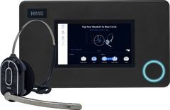
9. On the base station UI, follow the onscreen Installation
Wizard to configure and test the system.
Fig. 2.1
Note: If you accidentally exit the Installation Wizard
and need to return to it. LOG IN to the system,
go to SYSTEM, then the TROUBLESHOOTING tab, and
select “Installation Wizard” from the drop-down
menu. Tap the “Start Installation Wizard” button.
10. Critical Step: The Installation Wizard will prompt
you to use a paired headset switched to Reception
Location Mode. You will need to walk all areas
of the store where the headset will be used to
ensure a good signal. The Boom LED at the tip of
the Headset microphone flashes different colors
to indicate areas with a strong or weak reception.
See Fig. 2.2. Also see CAUTION Note in Step 5.
Note: Depending on the size and layout of the
store, some stores may require more than one
RT7000 to provide good coverage.
11. Once the optimal location for the RT7000s has
been verified, secure all the loosely mounted
system components.
12. Test audio levels between the headsets and the
drive-thru ordering points, adjust accordingly
using the volume controls on the base station UI.
Use cable ties to bundle and strain relief the
cables exiting the base station to one of the crossbars
on the rear housing.
14. Close the base station. The system is now ready
for use.
AC70 BATTERY CHARGER WALL OUTLET
Front/Top View
POWER ADAPTER
Note: Only use the HME approved Power Adapter provided
Storage ports do not charge batteries.
© 2022 HM Electronics, Inc. All rights reserved.
Component Notes
Installing the RT7000:
• The RT7000 is omnidirectional so mount the
RT7000 high in a central location to were the
headsets are typically used.
• Maximize line of sight between the RT7000 and
headsets in an area free from obstructions and
equipment/materials that can interfere with signal
propagation. These include walls, large metal
appliances, hoods, and backsplashes, etc.
• Mount the RT7000 vertically on a wall in the
upright position (see arrow on RT7000 rear). Do
NOT mount horizontally, such as on a ceiling.
This will reduce the RT7000’s range.
• The RT7000 uses an Ethernet (Cat5 or Cat6)
cable. Do not exceed 500’ (152 m).
• Large or multilevel premises may require more
than one RT7000. Up to four RT7000s are supported
by the base station (J3200 - J3800).
• Once connected to the base station, the center
LED on the RT7000 front illuminates to indicate
it is turned on. One of the outer
LEDs (numbered 1 to 4) also
turns on depending on what
base station port it is connected
to (1 is used in this example).
This outer LED will initially flash a
different color as the RT7000 scans for available
channels before turning solid green once a channel
is found (on the base station HOME screen,
the “Transceivers” indicator is yellow while scanning
before turning green).
• If mounting outside on an exterior wall, you must
use a lightning arrestor. HME provides these.
Base Station Power Supply:
1. Terminate the positive wire of the power supply to
J1 DC + terminal (pin 1).
2. Terminate the negative wire of the power supply
to J1 DC - terminal (pin 2).
3. Terminate the shield to J1 GND (pin 3).
Note: Only use the HME power supply provided with
your system.
IB7000 Connections:
The IB7000 must be mounted vertically, inside the
speaker post, close to the speaker/microphone. This
will help minimize audio hum and noise (thus, do
not mount the IB7000 too far away, such as inside
the store). Adhesive strips on housing allow the
IB7000 to be affixed to a clean, dry surface inside
the speaker post. All connectors are labeled.
• The two-pin Loop connector connects to the
ground loop.
• The three-pin PLC/BASE connector connects to
J4500 on the base station. Note: The shield/
drain must be grounded.
• The seven-pin DM5 MIC | SPKR connector connects
to the Microphone and Speaker. Note: Pins
4 and 5 are only used if connecting the SS7000
speaker.
• The five-pin RELAY | BCKP SPKR connector (optional)
connects to an intercom system like the
IC300 if a backup is needed in the event of a
system failure.
Note: If installing more than one IB7000. Take note
of the serial numbers so you know where each one is
Base Station opened assigned when configuring using the base station.
Component Notes
Installing the RT7000:
• The RT7000 is omnidirectional so mount the
RT7000 high in a central location to were the
headsets are typically used.
• Maximize line of sight between the RT7000 and
headsets in an area free from obstructions and
equipment/materials that can interfere with signal
propagation. These include walls, large metal
appliances, hoods, and backsplashes, etc.
• Mount the RT7000 vertically on a wall in the
upright position (see arrow on RT7000 rear). Do
NOT mount horizontally, such as on a ceiling.
This will reduce the RT7000’s range.
• The RT7000 uses an Ethernet (Cat5 or Cat6)
cable. Do not exceed 500’ (152 m).
• Large or multilevel premises may require more
than one RT7000. Up to four RT7000s are supported
by the base station (J3200 - J3800).
• Once connected to the base station, the center
LED on the RT7000 front illuminates to indicate
The AC70 Smart Battery Charger:
• The AC70 can be placed on a desk or mounted
on the wall (use template on page 4 for wall
mounting). Position the AC70 within 10 feet (3
m) of the base station if you wish to monitor your
battery status via the base station HOME screen.
• New BAT70 batteries must be charged, so begin
charging them immediately.
• The LEDs on the AC70 indicate charge status (see
AC70 LED Reference Table). Or, if placed within
range of the base station and the status indicator
is (green). Tap on the HOME screen
to view battery status.
Headset (AIO HS7000):
1. Install a charged
BAT70 battery into
the headset and
press the power button
to turn it on (see
Fig. 3.2). The LEDs
flash green and red.
2. Pair the headset by
holding the headset’s
keypad side
against the Headset
Pairing Ring (solid
blue circle) on the
base station (see
Fig. 3.3). Pairing
begins automatically
as soon as the
headset is sensed.
3. When the Headset Pairing Ring turns solid green,
pairing is successful (see note if pairing fails). The
Headset status LED also turns solid green.
4. Choose your position on the base station Home
screen and begin using the headset.
Note: If pairing fails (indicated by a red swirling ring), try
again. Hold the headset steadily centered and flush against
the Headset Pairing Ring (headset movement and distance
from the Pairing Ring can cause pairing errors).
J200 (Line In/Out)
Pin # Label Descptn/color
1 Line In
2 GND Ground
3 N/C Not connected
4 Line Out
5 GND Ground
(Ceiling Speakers)
Pin # Label Description/wire color
1 Ceiling Spkr1 + Speaker 1 positive
2 Ceiling Spkr1 - Speaker 1 negative
3 GND Ground
4 Ceiling Spkr2 + Speaker 2 positive
5 Ceiling Spkr2 - Speaker 2 negative
6 GND Ground
J4500 & J4501 (Spkr/Mic Interface)
Pin # Label Descptn/color
1 Spkr/Mic PL + Red to PLC IN1 - 1
2 Spkr/Mic PL - Black to PLC IN2 - 2
3 Shield Shield to PLC GND - 3
4 Spkr/Mic PL +
5 Spkr/Mic PL -
6 Shield
J803 (Early Warning Inputs)
Pin # Label Description/wire color
1 Erly Wrn In 1 Early Warn In 1
2 GND Ground
3 N/C Not connected
4 Erly Wrn In 2 Early Warn In 2
5 GND Ground
J804 (Remote Switch Inputs)
Pin # Label Description/wire color
1 GND Ground
2 OO in 1 Outside Order in 1
3 Ded in Dedicated In
4 OO in 2 Outside Order in 2
5 GND Ground
J805 (Alert/Alert Switch Inputs)
Pin # Label Description/wire color
1 Switch In 1
2 Switch In 2
3 Switch In 3
4 GND Ground
5 Switch In 4
6 Switch In 5
7 Switch In 6
8 GND Ground
Fig. 4.1
J201 (Telephone Interface)
Pin # Label Description/wire color
1 Tel Audio In
2 Tel Power +12V
3 Tel Off Hook
4 Tel PTT
5 Tel Ring
6 Tel Active
7 Tel Ground
8 Tel Audio Out
J800 and J801 (Lane 1 & 2 Timer)
Pin # Label Description/wire color
1 Greet Out Greet Out 1 for J800
Greet Out 2 for J801
2 GND Ground for J800 and J801
3 N/C Not connected
4 Alt Grt Out Alt Greet Out 1 for J800
Alt Greet Out 2 for J801
5 GND Ground for J800 and J801
6 Veh Det Out Com Veh Det Out Com1 for J800
Veh Det Out Com2 for J801
7 Veh Det Out N.O. Veh Det Out N.O.1 for J800
Veh Det Out N.O.2 for J801
8 Veh Det Out N.C. Veh Det Out N.C.1 for J800
Veh Det Out N.C.2 for J801
J802 (Ext. Vehicle Detect Inputs)
Pin # Label Description/wire color
1 +12 V Power
2 N/C Not connected
3 Veh Det In 1 Vehicle Detect In 1
4 GND Ground
5 Veh Det In 2 Vehicle
Tools/Equipment Needed
• General hand tools: Screwdrivers, cutters,
pliers, wire strippers, etc.
• Drill and drill bit set
• Tape measure, pencil/maker
• Cable Pull Equipment (fish stick/tape, pull
string, cable ties, etc.)
• Soldering Iron and solder.
• Crimp caps or shrink tubing with heat gun
• Serrated knife
• Safety glasses, ladder
• Acoustic Foam
• Audio Cable
Mounting Template for AC70
1. Hold template against wall,
2. Use a marker to punch through paper at
the crosshairs to mark the wall.
3. Mount using hardware provided (leave a
small gap between the screw head and
the wall so that the AC70 keyholes mount
over the screw heads, flush to the wall).
© 2022 HM Electronics, Inc. All rights reserved.