

 HME NEXEO | HDX™ Crew Communication Platform / Installation Guide
NEXEO | HDX™
Crew Communication Platform
Installation Guide
WHAT’S IN THE BOX
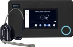
1. Base Station (BS7000) with power adapter
2. Headsets (HS7000) and batteries (BAT70)
3. Radio Transceiver (RT7000)
4. Battery Charger (AC70) with power adapter
5. Post Speaker/Mic (SM7000, shown), or IB7000 with DM5 Mic and SS7000 Speaker or SP10 (not shown)
6. Installation & User’s Guide
7. Hardware and cables (not shown)
8. Acoustic Foam (not shown)
The system contents in the box will vary depending on the customer’s order. Quantities of certain components such
as headsets and batteries will also vary. However, the components listed here consist of the basic components that
are generally included with a complete system.
TOOLS/EQUIPMENT/MATERIAL REQUIRED
General Tools/Equipment
• General hand tools, screwdrivers, cutters, pliers, and wrenches
• Standard Drill (for wall mounts)
• Drill bit set (sizes 1/16” - 1/2”)
• Wire strippers
• Soldering Iron and solder
• Tape measure
• Pencil/marker
• Crimp caps or shrink tubing with heat gun
• Serrated knife
• Cable pulling equipment: fish stick/tape, pull strings, etc.
• Ladder
Specialty Tools/Equipment
• N/A
Materials
• Cable ties (for bundling any cable slack, available at most hardware/home improvement stores).
• Hardware (while general hardware is provided for mounting system components, there may be situations when
specialty hardware is required such as masonry screws for brick or concrete walls).
• Electrical tape, twist caps
• Audio cable
• Acoustic Foam
Safety Equipment
• Safety Glasses
• ESD grounding strap (for connecting to the PCBA in the Base Station)
FCC Certification and More:
Regulatory and Compliance information can be found online by going to Drive-Thru Headset Systems>NEXEO |
HDX at: https://www.hme.com/qsr/drive-thru-user-manuals/
Disclaimer
HM Electronics, Inc. is not responsible for equipment malfunctions due to erroneous translation of its publications
from their original English version. Illustrations in this publication are approximate representations of the actual
equipment, and may not be exactly as the equipment appears. They are subject to change without notice.
Before you begin
Survey the premises with store manager to determine the optimal mounting locations for each component.
Take into consideration:
• The system requires a region code to function, so an internet connection and an HME CLOUD account
are necessary. Connect and verify first before installing the RT7000.
• Cable lengths for the hardwired components such as the remote transceiver, network connections,
etc., which may limit the possible locations available.
• Proximity to power outlet and network router.
• If mounting the Base Station in an area with high foot traffic, take into consideration carts and mobile
shelving units, which can damage the Base Station if impacted.
• Finding a good location for the remote transceiver is critical (see Fig. 2.8, and 2.9). Also read about
the “Remote Transceiver (RT7000)” on page 14 under Component Notes and review the Critical
Steps in these instructions.
The Base Station and Connections
The Base Station is the control center and focal point of the NEXEO | HDX™ system. System features are
configured here and all connections are terminated here. This is also where store personnel interact with
the system when setting up profiles and pairing headsets. If you are replacing an existing HME product
such as an EOS|HD® system, mounting the Base Station close to the same location of the Base Station
you are replacing will enable you to use the existing wires/cables without having to route new wires.
However, verify the wires/cables are in good condition before using.
CAUTION: Wear proper eye, ear, and body protection when grinding or drilling. Be familiar
with the manufacturer’s safety information and operational instructions for tools and materials.
Be aware of your surroundings. Failure to heed such precautions can cause injury and/
or property damage. Before drilling, also make sure the area behind the wall is free from
electrical wiring and plumbing.
Installing the System
1. The base station should be mounted in a location easily accessible
by all crew members at all times (i.e., not in a locked office
with limited access).
2. Mount the Base Station at an optimal height from the floor with
the touchscreen visible and within easy reach to comfortably operate
with fingers. The mounting height should be between shoulder
and eye level for someone of average height (see Fig. 2.1).
Note: Mounting height should also take into consideration
personnel with disabilities, such as those requiring the use of a
wheelchair.
3. There are two latches along the top side of the Base Station (see
Fig. 2.2). Unlatch these to open the Base Station cover (the cover
does not completely detach as it is hinged on the bottom side).
Four mounting holes are visible, one at each corner through
the legs (see Fig. 2.3). Use a pencil to mark the wall
through these holes (avoid touching the exposed PCBA
unless you are wearing a ground strap). Drill four pilot
holes (3/16” drill bit). Push the four plastic anchors into
the holes until flush and insert the four screws provided,
but do not tighten. Leave enough space to mount the
Base Station over the head of the screws and slide into
the slots. Tighten screws to secure the Base Station.
4. Mount the power supply. Mark the mounting location
on the wall through the mounting holes on each side.
Mount the power supply using the hardware provided.
Terminate the power supply to the Base Station (see
“Wiring Diagram’s” Fig. 2.10, 2.11 and wiring connections
on page 5).
5. Critical Step: Loosely mount and connect the RT7000
(Fig. 2.4 & 2.5) in a central location for optimal coverage
(until range tested in steps 9 & 10 with the Installation
Wizard). For example, notice Fig. 2.10 and
2.11. They show two different store layouts with specific
targeted areas where the headsets are primarily used.
In these examples, the location selected for the RT7000
(represented by the small blue rectangle) offered the
best coverage indicated by the blue circled areas. Each
store required the RT7000 to be mounted in a different
but central location to provide the best all-around
coverage unique to the store’s need. Store layout and
obstructions also affected placement and range. (see
“Component Notes” on page 14 for more details on
the RT7000 placement).
CAUTION: If the RT7000 needs to be relocated,
wait at least 5 seconds after unplugging it before reconnecting
the cable to the same base station port.
This allows time for the system to turn off power to
the port, connecting to a live port can damage the
circuitry. Or, reconnect it to a different port.
6. Install the other components such as the post speakers,
etc. If installing a new system with Speaker/Mic SM7000
use Fig. 2.12 as a wiring reference.
However, if connecting a DM5 microphone and SS7000
speaker or SP10 speaker, you must also use the IB7000.
Use Fig. 2.13 as a wiring reference and see “Component
Notes.” for more installation details.
7. Route and terminate all component cables to the Base
Station using the wiring references in this guide. Consult
the store’s IT personnel when connecting to the network
router.
8. Terminate the Base Station power supply and connect to
outlet. The Base Station turns on automatically and will
perform a self-check to determine that all is good and
ready to go.
9. On the Base Station UI, follow the Installation
Wizard to connect and configure the system (see
Fig. 2.6).
Note: If you accidentally exit the Installation
Wizard and need to return to it. LOG IN to the
Base Station, go to SYSTEM, then the TROUBLESHOOTING
tab and select “Installation Wizard”
from the drop-down menu. Tap the “Start Installation
Wizard” button.
10. Critical Step: At the Configure stage of the
Installation Wizard, the Transceiver Installation
Step 2 screen prompts you to use a paired
headset switched into Reception Location Mode
(Fig. 2.7). When you pair a headset at this step,
the Reception Location Mode indicator turns
from OFF to ON (Fig. 2.8). Tap “Continue”
to move to Transceiver Installation Step
3. You will need to walk all areas of the store
where the headset will be used to ensure a good
signal. The Boom LED at the tip of the Headset
microphone flashes different colors to indicate
areas with strong or weak reception (The NEXEO
screen displays this color-coded range which is
also shown here in Fig. 2.9). Depending on the
results, you may have to reposition the Remote
Transceiver before finding the optimal location.
Note: Depending on the size and layout of the
store, some stores may require more than one
Remote Transceiver to provide adequate coverage.
Also see CAUTION note for Step 5.
11. Once the optimal location for the Remote Transceiver
has been verified. Secure all the loosely
mounted system components.
12. Test audio levels between the headsets and the
drive-thru ordering points, adjust accordingly using
the volume controls on the Base Station UI.
13. Use cable ties to bundle and strain relief the cables
exiting the Base Station to one of the crossbars
on the rear housing.
14. Close the Base Station. The system is now ready
for use.
Note: See “Component Notes” on page 14 for
more details on system components and installation.
If you are alerted concerning a fault or failure,
verify the system is configured properly through the
Installation Wizard found under SYSTEM>TROUBLESHOOTING.
Also, reference “Help” on page
25 of this guide.
INSTALLATION WIZARD OVERVIEW
Once the system is installed and connected, the Base Station turns on automatically when plugged into an electrical
outlet. The Installation Wizard is the first screen you’ll encounter if the Base Station is new and not yet configured.
You will need your installer’s password to access the Installation Wizard. The following information gives you an
overview of the Installation Wizard but does not show every screen or step involved in completing the installation.
The Installation Wizard will guide you through this process.
There are three main setup stages: Welcome, Connect, and Configure. Each stage has several sequential steps
(screens), and are completed in order to advance to the next step unless you have the option to “Skip.” Completed
stages are indicated by a checkmark (e.g., in Fig. 3.2). The current stage you are in is indicated in blue
(e.g., in Fig. 3.1), while stages yet to be completed are in gray.
Stage 1: Welcome
This screen, prompts you as to what is needed before continuing.
Fig. 3.1
Click the blue Continue button to proceed. This next screen provides you with an overview of the Installation Wizard
stages. You have a choice of Manual Setup or Use Wizard. We recommend you use the Wizard.
Stage 2: Connect
This stage connects the system. DHCP stands for Dynamic Host Configuration Protocol and allows a network
administrator to supervise and distribute IP addresses from a central point. When the DHCP is enabled, the system
automatically populates the required fields. Consult the Glossary if you need a definition of other fields used here.
© 2022 HM Electronics, Inc. All rights reserved. 13
Stage 3: Configure
This stage configures the system. Lane setup, Transceiver positioning, and headset registration are performed here.
Fig. 3.3
Note: If you accidentally exit the Installation Wizard and need to return to it. LOG IN to the system, go to
SYSTEM, then the TROUBLESHOOTING tab and select “Installation Wizard” from the drop-down list. Tap the
“Start Installation Wizard” button to begin (see Fig. 3.4).
COMPONENT NOTES
Cable Pulling
This section is only applicable if you are routing new cables and not using the existing cables from a system you are
replacing.
CAUTION: Never run high-voltage cables in the same conduit with audio or loop cables.
1. Run fish tape from inside the building, through the conduit to the speaker post or menu board.
2. Go outside for the cable going to the speaker post. If you are pulling more than one identical cable, mark the
cables and spools for identification. Fasten each cable to the fish tape where it comes out of the conduit.
3. Pull the fish tape and cable through the conduit into the building. Disconnect the cable from the fish tape and
pull enough of it in to reach the base station.
4. Go outside again and route the cable from the outside conduit to the speaker in the speaker post or menu
board.
5. Cut the cable, leaving about 3 feet (91 cm) of slack (or enough length to easily route the cable through the
speaker post and terminate it). If more than one cable has been pulled, mark the ends of the cables again for
identification.
6. Remove about 2 inches (5 cm) of the out insulation from the end of each cable. Strip about 1/2 inch (12 mm) of
insulation from each of the wires in the cable.
7. Route all the cables together to the base station, through walls and over ceiling panels if possible. Make sure
that any cable slack is bundled, secured and out of the way if left in the ceiling or elsewhere.
Remote Transceiver (RT 7000)
The RT7000 Remote Transceiver (Fig. 4.2) is a required
component that facilitates Base Station to Headset communication.
It uses a wired connection to the Base Station
but is wireless in communicating with Headsets. Up to
four RT7000s can be connected to the Base Station to
provide greater coverage for larger or multi-level premises.
Installing the Remote Transceiver (RT7000):
• The RT7000 is omnidirectional so mount the RT7000
high in a central location to where the headsets are
typically used (see Fig 4.1).
• Maximize line of sight between the transceiver and
headsets in an area free from obstructions and
equipment/materials that can interfere with signal
propagation. These include walls, large metal appliances,
hoods, and backsplashes, etc.
• Mount the transceiver vertically on a wall in the upright
position (see Fig. 4.4 and orientation arrow on
the RT7000 rear). Do NOT mount horizontally such
as on a ceiling, this will severely reduce the transceiver’s
range.
• The RT7000 uses an Ethernet (Cat5 or Cat6) cable.
Do not exceed 500’ (152 m).
• Large premises may require more than one Transceiver.
Up to four Transceivers are supported by the
Base Station ( PCBA ports: J3200, J3400, J3600, and J3800).
• Once connected to the Base Station, the LED in the middle of the circle
on the transceiver front illuminates to indicate it is turned on. One of
the outer LEDs (numbered 1 to 4) around the circle
also turns on (depending on which port the Transceiver
is connected to on the Base Station, see Fig.
4.3 and Table 1). This outer LED will initially flash a
Magenta, blue or yellow color (see Table 2) as the
Transceiver scans for available channels before turning
solid green once a channel is found (on the Base
Station HOME screen, the Transceivers’ indicator is
yellow while scanning before turning green).
Remote Transceiver ports on Base Station PCBA
Connector Label Status/Description To LED #
J3200
J3400
J3600
J3800
Remote XCVR Module 1
Remote XCVR Module 2
Remote XCVR Module 3
Remote XCVR Module 4
First RT7000
Second RT7000
Third RT7000
Fourth RT7000
1
2
3
4
Table 1
* RT7000s can be connected to any port in any order and do not have to follow this table.
RT7000 LED Colors with Functional Description
Color (LEDs 1-4) Functional Description
Green (Solid)
Magenta (Blinking)
Yellow (Blinking)
Yellow (Solid)
Blue (Blinking)
Cyan (Blinking)
Red (Solid)
Ready for use. RT7000 is broadcasting, and Headsets
can connect.
WiFi Scan.
Radar Scan.
RT7000 is in Test Mode.
Main radio or Radar1 radio is updating.
Radar2 radio is updating.
RT7000 has reset and is starting initialization.
Table 2
• If the RT7000 is mounted outside on an exterior wall, a surge protector/lightning arrestor must be used, see
Fig. 4.5. The ground lug supports up to 12 AWG wire but check with your municipality for local codes on appropriate
grounding. With bidirectional protection, either RJ45 jack can be used. Contact HME if one or more
are required.
The Smart Battery Charger (AC70)
The AC70 Battery Charger can charge up to four BAT70 lithium-
ion batteries at the same time. LEDs at the charging ports
indicate battery status. Charge time is two hours. The AC70
can be used on a desktop or mounted on a wall.
INSTALLATION/SETUP AND OPERATION
Desktop instructions:
1. Place the AC70 on a level desktop or shelf.
2. Connect the power adapter to a wall outlet, and the
other end to the power connector on the AC70 (Fig. 5.1
& 5.2).
3. Position the BAT70 battery correctly for insertion into the
AC70 (it is keyed and can only be inserted one way).
4. Insert the BAT70 battery into a vacant port to begin
charging. LED activity indicates battery status (see table
below).
Battery Charger LED Reference Table
LED Color Status/Description
Green Flashing Green = Charging
Solid Green = Fully charged
Red Flashing Red = Incompatible battery
Red/Yellow Flashing Red & Yellow (alternating)= Fault
condition
Base Station HOME screen
Status Indicators
Note: The AC70 requires close physical proximity (<10 ft (3 m)) to the base station if you desire to monitor battery
status via the base station HOME screen. When within range, the Chargers indicator on the HOME screen changes
from to (gray to green). Once green, tap to view battery status, see Fig. 5.3.
CHANGING POWER SUPPLY ADAPTER
1. Replace power adapter (P/N: CON-00004) to match Press in here on both sides of latch to release
Slide in these directions to remove and replace
Latch
Adapter
your country’s outlet by using your thumb and
forefinger to squeeze in on both sides of the latch
(see Fig. 5.4).
2. Continue squeezing latch and slide the adapter out,
away from the power supply to remove.
3. Release the latch and slide another adapter on until it
bottoms out and the latch clicks to secure it in place.
WALL MOUNTING TEMPLATE FOR AC70
1. Hold template against wall.
2”
(50.8 mm)
2. Use a marker to punch through the paper
template at the two crosshairs to mark the
wall.
3. Drill two holes at the marks on the wall (avoid
electrical or plumbing obstructions).
4. Install the provided hardware but do not tighten,
leave a gap (~ ¹/8th inch (3.2 mm)) between the
screw heads and wall.
5. Align the AC70 mounting keyholes with the two
screws.
6. Mount the AC70 over the screw heads until flush
against the wall, then slide it down onto the
screw shanks to secure it in place.
Headset (HS7000)
The AIO HS7000 Headset (Fig. 6.1) is an all-in-one headset used to communicate with fellow employees and
customers in a drive-thru lane environment. It uses one BAT70 lithium-ion battery. Under normal use, the headset
will operate for approximately 8 hours on a single battery charge (new battery) and will alert you when the battery
charge is low. The Omni headset (not shown) uses a detached keypad but the functionality is identical to the AIO.
HME
Power Button
(blue)
BAT70 Battery
(not included)
HEADSET
Front View
HEADSET
Side View
Earpad
Lane 1 Lane 2
Raised sections on
the bezel allow users
to identify keypad
buttons by touch.
Status
LED
Boom
LED
Status
LED
Volume Up
Volume Down
Action Group Chat
Battery Release
Latch (silver)
Fig. 6.1
Keypad Reference Table
Icon Label Status LED Boom LED Status/Description (voice commands are initiated by saying “Ok Nexeo” first)
Lane 1 Green Green Tap to talk to lane 1. The Status LED flashes green while the Boom LED turns on solid
green. Tap again to stop. The Status LED turns solid; the Boom LED turns off.
Voice Command: “lane 1” (to listen only) or “talk to lane 1,” or “change lane” if in lane 2
Lane 2 Red Red Tap to talk to lane 2. The Status LED flashes red while the Boom LED turns on solid red.
Tap again to stop. The Status LED turns solid; the Boom LED turns off.
Voice Command: “lane 2” (to listen only) or “talk to lane 2,” or “change lane” if in lane 1
Volume
Up
Tap to increase volume (the headset beeps become louder as confirmation). Press and
hold to maximize volume to loudest. Voice Command: “volume up” or “volume #”
Volume
Down
Tap to decrease volume (the headset beeps become quieter as confirmation). Press and
hold to minimize volume to quietest. Voice Command: “volume down” or “volume #”
Group
Tap for group chat. Both Status and Boom LEDs flash quickly, alternating red & green. Tap
again to stop.
Action No Function. Reserved for future functionality.
Notes: Both the Status and Boom LEDs flash slowly alternating colors when the headset needs to be paired. A yellow Status
LED indicates a low battery. The low battery Status LED is also accompanied by audio prompts.
Voice commands can be used instead of tapping the keypad but must first be enabled on the Base Station. To use voice commands,
begin by saying “Ok Nexeo,” then, once the Boom LED turns on white continue with a voice command (see above table
for specifics). Volume # levels are 0-15. (E.g., saying: “Ok Nexeo, volume 12,” changes the volume level to 12. Mute is 0).
© 2022 HM Electronics, Inc. All rights reserved. 19
SETUP AND OPERATION
Note: The HS7000 is wireless and has an optimal
range in which signal strength is best. This is dependent
on the location of the Remote Transceiver
RT7000 and line of sight between both devices.
1. Insert a fully charged BAT70 battery into the
battery holder of the headset (see Fig. 6.1).
The battery clicks securely into place.
2. Press the blue power button to turn on the
headset (see Fig. 6.1). The status LED turns on
green and blinks, alternating between green
and red, indicating you now need to pair the
headset.
3. Hold the keypad side of the headset against
the Headset Pairing Ring (solid blue circle) on
the Base Station to pair. Pairing begins automatically
as soon as the headset is sensed.
The circular blue light turns a swirling green
to indicate pairing is in progress (see Fig. 6.2).
4. When the Headset Pairing Ring turns solid green, pairing is successful (registration also happens automatically
with the initial pairing). If pairing fails, see note.
5. Select your position and begin using the headset.
Notes: A swirling red light indicates an unsuccessful pairing. Try again by first verifying that the headset is on, and
the battery is fully charged. Hold the headset steadily centered and flush against the Headset Pairing Ring (headset
movement and distance from the Pairing Ring can cause pairing errors).
A weak battery might also result in pairing issues. To replace the battery, press the battery release button above the
battery compartment (Fig. 6.1) and remove by sliding battery out. Insert a fully charged battery by sliding into the
battery compartment until it bottoms out and clicks securely in place.
INSTALLING THE SM7000
The SM7000 is a speaker/microphone combination (Fig. 7.1).
It is designed for use in Quick Service Restaurant (QSR) menu
boards, speaker posts, and enclosures. Also see the NEXEO |
HDX system Installation Guide for more details.
Note: When using the SM7000, ignore the section “Installing
the Microphone, Speaker and IB7000.”
Tools/Equipment Required
• General hand tools: screwdrivers, cutters, pliers, wire
strippers, etc.
• Serrated knife
• Audio Cable (not included)
• Acoustic Foam (not included)
These instructions are for a typical installation.
1. Strip approximately 1 inch (25.4 mm) of insulation from the
end of the audio cable and ¼ inch (6.35 mm) of insulation
from each of the cable wires, but do not tin the wires. Connect
the audio cable wires to the connector plug. Note: The
Shield must also be terminated.
2. Insert the connector plug into the three-pin PLC/BASE
speaker connector (see Fig. 7.2).
3. In like manner, terminate the ground loop wires to the twopin
Loop connector.
4. Position the speaker inside the speaker post or menu
board, with the gasket centered against the inside of the
speaker grill; see Fig. 7.3. Align the opening in the gasket
with the grill opening. Notes: If more than
one location is available, choose the one closest
to the driver’s window level. The SM7000 should
be pushed flush against the post to prevent audio
issues. If the speaker post opening is small, position
the speaker (lower section of the SM7000) closest
to it.
5. Remove both inserts from the molded foam enclosure
and place the foam enclosure around the
speaker. Trim foam with a serrated knife if necessary.
Place removed foam inserts behind speaker
to provide pressure to speaker, to ensure a good
gasket seal against the speaker grill opening.
6. Connect the other end of the audio cable to the
J4500 on the base station. See Fig. 2.12 and “Wiring
connections (Not all connections are required)”
on page 4.
Note: The five-pin RELAY | BCKP SPKR connector is optional and is used to connect to an intercom system
like the IC300 if a backup is needed.
INSTALLING THE MICROPHONE, SPEAKER AND IB7000
Note: This section is only necessary if not using the SM7000
The DM5 Microphone
The DM5 must be used in conjunction with the IB7000 interface
box (i.e., the Microphone does not connect directly to the base
station).
• See Fig. 2.13 for visual reference and IB7000 section
for wiring tables.
Typical DM5 Microphone installation involves placement of the
microphone in a molded foam enclosure and mounting it inside
the upper compartment of the speaker post. You will fill the
empty space behind the unit with acoustic foam. If the DM5
is mounted in a small area, its molded foam enclosure may
need to be compressed in order to close the compartment.
Follow these instructions to install the DM5 in a typical
speaker post or menu board.
1. Open the speaker post and remove any existing equipment,
foam or debris. If there is an existing microphone,
remove it and disconnect the microphone cable.
2. Remove the small portion of the provided foam microphone
enclosure, resulting in the two pieces of foam
shown in Fig. 8.2.
3. Insert the DM5 Microphone cable through the hole in
the foam enclosure, and place the microphone into the
hole as shown in Fig. 8.2.
4. Insert the removed piece of foam back into the hole in
the foam enclosure to fit snugly against the back of the
microphone, as shown in Fig. 8.2.
5. Using a serrated knife, trim the foam enclosure so it is
¼ to ½ inch larger than the upper speaker post compartment
(vertically and horizontally) for a compressed
fit. Keep the foam pieces to fill the compartment (if
needed).
6. Place the foam windscreen in front of the microphone,
positioning it to cover the inside of the speaker grill as
shown in Fig. 8.3.
7. Place the foam enclosed microphone into the compartment,
so the front of the microphone windscreen is flush
against the metal, centered on the grill, see Fig. 8.3.
8. The DM5 wires are connected to terminals 1, 2, and
3 of the seven-pin DM5 MIC | SPKR connector on the
IB7000. See Fig. 2.13 and “Wiring connections (Not all
connections are required)” on page 4.
9. Pack acoustic foam in the empty space behind the DM5
Microphone and its foam enclosure, filling the space.
The SS7000 Speaker (if not using the SP10)
The SS7000 must be used in conjunction with the
IB7000 interface box (i.e., the speaker does not connect
directly to the base station).
• See Fig. 2.13 for visual reference and IB7000
section for wiring tables.
These instructions are for a typical installation.
1. Strip approximately 1 inch (25.4 mm) of insulation
from the end of the audio cable and ¼ inch (6.35
mm) of insulation from each of the four cable
wires, but do not tin the wires. Connect the audio
cable wires to the connector plug (the speaker
connector is labeled).
2. Insert the connector plug into the speaker connector
(see Fig. 9.2).
3. Position the speaker inside the speaker post or
menu board, with the gasket centered against
the inside of the speaker grill, as shown in Fig.
9.3. Align the opening in the gasket with the grill
opening.
4. Remove both inserts from the molded foam enclosure
and place the foam enclosure around the
speaker. Trim foam with a serrated knife if necessary.
Place removed foam inserts behind speaker
to provide pressure to speaker, to ensure a good
gasket seal against the speaker grill opening.
5. Connect the other end of the audio cable to the
IB7000. The four wires on the SS7000 connect to
terminals 4,5, 6, and 7 of the seven-pin DM5 MIC
| SPKR connector on the IB7000 (this connector is
labeled on the IB7000), see Fig. 2.11.
6. Connect audio cable between the three-pin PLC/
BASE connector on the IB7000 and J4500 on the
base station (this connector is also labeled on the
IB7000). See Fig. 2.13 and “Wiring connections
(Not all connections are required)” on page 4.
Note: You may be able to use the existing audio
cable if replacing an older HME system like EOS.
Verify the cable is in good condition before doing
so.
The SP10 Speaker (if not using the SS7000)
The SP10 must be used in conjunction with the IB7000
interface box (i.e., the speaker does not connect directly
to the base station).
• See Fig. 2.13 for a visual reference and IB7000
section for wiring tables.
1. Strip approximately 1 inch (25.4 mm) of insulation
from the end of the speaker cable, and ¼ inch (6.35
mm) of insulation from each of the two cable wires,
but do not tin the wires. Connect the speaker cable
wires to the connector plug as shown in Fig. 10.2.
Insert the connector plug into the connector on the
speaker as shown in Fig. 10.2.
2. Remove the double-stick tape liner, and press the
adhesive side of the gasket against the front of the
speaker in the position shown in Fig. 10.2.
3. Position the speaker inside the speaker post or menu
board, with the gasket centered against the inside of
the speaker grill as shown in Fig. 10.3. The cable
connector can be routed to either side. Align the
opening in the gasket with the grill opening.
4. Remove both inserts from the molded foam enclosure
and place the foam enclosure around the
speaker. Trim foam with serrated knife if necessary.
Place the removed foam inserts behind speaker to
provide pressure to speaker, to ensure a good gasket
seal against the speaker grill opening.
5. The SP10 wires are connected to terminals 6 & 7 of
the seven-pin DM5 MIC | SPKR connector on the
IB7000 (this connector is labeled on
the IB7000).
6. Connect audio cable between the
three-pin PLC/BASE connector on
the IB7000 and J4500 on the base
station (this connector is also labeled
on the IB7000). See Fig. 2.13 and
“Wiring connections (Not all connections
are required)” on page 4.
Note: You may be able to use the
existing audio cable if replacing an
older HME system like EOS. Verify
the cable is in good condition before
doing so.
The IB7000 (required for DM5 & SS7000 or SP10. not required for SM7000)
The IB7000 interface box is required if you are connecting
the DM5 and SS7000 speaker or SP10 speaker to the NEXEO
system (i.e., these components do not connect directly to the
Base Station).
IB7000 Connections:
Fig. 2.13 on page 11 shows how the IB7000 is typically connected.
Adhesive strips on housing allow the IB7000 to be
affixed to a clean, dry surface inside the speaker post.
Note: The IB7000 must be mounted vertically, inside the
speaker post close to the speaker/microphone. This will help
minimize audio hum and noise (thus, do not mount the IB7000
too far away such as inside the store). If more than one IB7000
is being installed, take note of the serial numbers so you know
where each is assigned when configuring on the base station.
• The two-pin Loop connector connects to the ground loop.
• The three-pin PLC/BASE connector connects to J4500 on the base station. This connection requires
the shield/drain to be grounded; see Table 1.
• The seven-pin DM5 MIC | SPKR connector connects to the Microphone and Speaker; see Table 2.
• The five-pin RELAY | BCKP SPKR connector (optional) connects to an intercom system like the IC300 if
a backup is needed in the event of a system failure.
IB7000 PLC connector to Base Station J4500/J4501 (Spkr/Mic Intrfc)
Pin # IB7000 PLC Label Pin # Base Station J4500/J4501 Label
1 IN1/PL+ (Red wire) 1 Spkr/Mic PL +
2 IN2/PC- (Black wire) 2 Spkr/Mic PL -
3* GND - (Shield/drain) 3 Shield
4 Spkr/Mic PL +
5 Spkr/Mic PL -
6 Shield
Table 1
IB7000 DM5 MIC | SPKR connector to Speaker and Mic
Pin # IB7000 Label Description/wire color Speaker/Mic labels
1 Mic + Ext. Microphone positive DM5 +ve (red)
2 Mic - Ext. Microphone negative DM5 -ve (black)
3* GND Mic Shield (must be terminated) DM5 Drain/Shield
4** I.D. 1-WIRE I/F (Red) Only for SS7000
5** GND Ground (Black) Only for SS7000
6 Spkr - Speaker negative (White) SS7000 or SP10 -ve
7 Spkr + Speaker positive (Green) SS7000 or SP10 +ve
Table 2
* The Shield/Drain on the DM5 and audio cable from the IB7000 PLC must be grounded.
** Pins 4 and 5 are only used if connecting an SS7000 speaker (not used with SP10).
© 2022 HM Electronics, Inc. All rights reserved. 25
AOT (AUTOMATED ORDER TAKING)
Automated Order Taking (hereafter AOT) requires a connection with a service provider. Please contact
your brand/chain for further information. It’s a voice AI feature that uses a bot to take customer orders in
the drive-thru so that staff are available to perform other roles in the restaurant. It is disabled by default.
Automated Order Taking: Toggle the OFF switch to ON to enable.
AOT MQTT IP: This is the IP of the MQTT broker. Any valid IP v4 is accepted. The default value is
0.0.0.0.
AOT IP: This setting is for future use and is not required at this time. The default value is 0.0.0.0.
AOT MQTT PORT: This is the port used by the MQTT Broker to listen to client connections. Valid values
are 8883 and 1883. The default value is 8883.
HME RTSP PORT: This is the port used by the Streaming Server to listen to streaming client connections.
Accepted values are integers between 1024 and 65535. The default value is 10000.
KEEP ALIVE INTERVAL: This is the interval in seconds, used to send keepalive messages to keep the
MQTT connection open with the MQTT Broker. A value of 0 will deactivate this mechanism. Values between
0 and 120 are accepted. The default value is 60.
TELEMETRY INTERVAL: This is the interval in seconds, used to send Telemetry messages to the MQTT
Broker. A value of 0 disables the Telemetry messages. Values between 0 and 120 are accepted. The
default value is 60.
READY HEARTBEAT INTERVAL: This is the interval in seconds, used to send the Heartbeat messages to
the MQTT Broker. A value of 0 disables the Heartbeat messages. Values between 0 and 120 are accepted.
The default value is 60.
HELP
HME Technical Support: If the help provided in this section is not sufficient, please contact our Technical Support
team at support@hme.com or call us at 1-800-848-4468. As a valued customer, we are here to help you have the
best experience with your product; your success is our success!
Troubleshooting
Problem Solution
The Base Station is off (blank
screen)
The Base Station does not have a power on/off button, it turns on automatically
once it is plugged into a live outlet.
Verify the power adapter is plugged into a live wall outlet.
Verify the power cable is properly terminated to J1 on the Base Station
PCBA and that there is power from the power adapter to this end of the
cable (illuminated LEDs on the PCBA indicate there is power to the base
station).
The Base Station is on but not
responsive to certain actions
The entire HOME screen is not
responsive to touch
Log in to the base station, go to SYSTEM, click on the troubleshooting tab,
select from the menu and try restarting the component that is not responsive.
Restarts can take several minutes to complete.
Try a hard reset by unplugging the power cord from the wall outlet. Wait a
few seconds and then reconnect power. Reboots can take several minutes
to complete.
The headset does not power on Verify the BAT70 battery is fully charged and not dead (verify charge in
AC70).
Verify the BAT70 battery is inserted correctly and properly docked (you
should hear an audible click when it is properly inserted and securely seated).
Verify the Power button depresses when pressed.
Verify the battery contacts in headset battery holder and on the battery are
clean and free of debris.
Verify the battery is the correct type (only HME BAT70 batteries are valid,
the battery is labeled on the back),
The headset does not pair Verify the headset has a sufficiently charged battery and that the headset is
powered on (the headset status LED illuminates).
Hold the headset steady, centered, flush against the headset pairing ring.
Movement and proximity can cause pairing failures.
The headset has no sound Verify the headset is on.
Verify the headset is paired.
Verify the headset is within range of the transceiver.
Press and hold the volume up button on the headset keypad, an audible
beep gets louder as volume increases.
Headset communication is choppy
or drops off
Headsets have an effective range based on the location of the RT7000
transceiver. Move the headset to within range of the transceiver.
Large objects can also interrupt signal propagation. Try moving to a different
location.
Verify the headset has a charged battery.
© 2022 HM Electronics, Inc. All rights reserved. 27
Problem Solution
Headset battery will not charge Verify the charger is plugged in and on.
Verify the battery is the correct type (BAT70).
Verify the battery is docked correctly in the port (the battery is keyed so it
can only be inserted one way. It should not be forced into the charging
port).
Verify the battery and charger contacts are clean and free from debris,
contaminants, or obstructions.
Verify battery is not dead. Batteries have lifespan, they will eventually die
and will need to be replaced. The Base Station monitors battery charge
cycles and informs you when to replace a battery. The AC70 needs to be
within 10’ (3 m) of the Base Station to monitor battery status.
RT7000 Transceiver not working Verify that the Ethernet cable is good, and connected on both ends. The
RT7000 Power LED illuminates when the Base Station is on.
When disconnecting the RT7000 from a Base Station that is powered on,
you must wait at least 30 seconds before reconnecting the RT7000 Ethernet
cable. This allows the system time to sense the disconnection and turn
power to the port off. Reconnecting to a live port can damage the circuitry.
If a port is damaged, try connecting to another one.
AOT Troubleshooting
Problem Solution
Audio streaming is not flowing between
NEXEO and the QSR Audio
Service
• Verify that IB7000/SM7000 version is 2.11.4 or higher and they are
connected to the base.
• Verify in AOT Settings screen that Automated Order Taking is enabled,
MQTT IP and PORT are set correctly, and RTSP Port is configured using
the value used by the QSR Audio Service to connect to the Streaming
Server.
• Download AOT logs and verify that MQTT is sending messages
correctly (Heartbeat, Telemetry, Arrivals, etc). Then validate that the
StreamingServer is up and running and that streaming client’s connection
is established.
• Re-start the NEXEO base if MQTT or Streaming Server are not responding
(not logging any information).
Audio streaming is not flowing
between QSR Audio Service and
NEXEO
• Verify in AOT Settings screen that Automated Order Taking is enabled,
and RTSP Port is configured using the value used by the QSR Audio
Service to connect to the Streaming Server.
• Validate that the IB7000/SM7000 is connected to the base.
• Validate that there is not headset connected to that lane with the microphone
open.
• Download AOT logs and verify that the StreamingServer is up and running
and that streaming client’s connection is established.
• Re-start the NEXEO base if Streaming Server is not responding (not
logging any information)
Problem Solution
Escalation tones are not playing • Verify that there is a car present on the lane where the escalation should
be played.
• Verify that the escalation messages are present on the base, going to
the Message Center, and validating that the 4 AOT Escalation messages
are available.
• Verify that the audio files associated with the escalation messages are
also present on the base, going to the Message Center -> Audio Files
tab, and validating that the 2 AOTEscalation files are there.
• Download AOT logs and verify that the MQTT escalation message has
been received on topic aot/request/auto-escalation/lane1 or aot/request/
auto-escalation/lane2.
MQTT Telemetry and Ready messages
are not being sent, while
other messages are
• Download AOT logs and verify that the StreamingServer is up and
running.
• Send a re-start command via MQTT message from the QSR MQTT
services.
• Re-start the NEXEO base if Streaming Server is not responding (not
logging any information).
LEDs
The System uses LEDs on components to indicate the status of the device.
LED Description
AC70 Charger: RED LED A (flashing red) LED indicates an unauthorized or unrecognized
battery. Only HME approved (p/n BAT70) lithium-ion batteries can
be used with your system.
Caution: Batteries not approved by HME will not charge
properly and can cause damage to the system, including explosions
with the potential to shock, inflict personal injury and/or
start fires.
HME cares about the environment. Please check with your
municipal laws, regulations, and guidelines for the proper
disposal of dead lithium-ion batteries.
AC70 Charger: RED/YELLOW LED Flashing Red & Yellow (alternating)= Fault condition other than an
unrecognized.
If you cannot resolve problems with the information presented here, please contact HME Technical Support
at 1-800-848-4468.
Additional Troubleshooting
If your system malfunctions, a red indicator on the HOME screen will alert you to where the problem
is (see color-code definitions below). Then, try resetting the system component in question via the Base
Station. For example, if the problem is the Speaker/Mic Posts:
1. Select SYSTEM from the sidebar menu.
2. Log in to the system.
3. Select the TROUBLESHOOTING tab.
4. Choose Speaker/Mic Posts from the drop-down list.
5. Tap on the Restart Speaker/Mic Post button and follow the prompt to reset.
Or, try reseting the system:
1. Select SYSTEM from the sidebar menu.
2. Log in to the system.
3. Select the TROUBLESHOOTING tab.
4. Choose Base Station from the drop-down list.
5. Tap on the Restart Base Station button and follow the prompt to reset.
Electrical Power Outage: If your system fails to function properly after an electrical power outage, power
the system off and unplug the AC power adapters from their electrical outlets. Wait a few seconds, then
plug them back in and power the system back on.
A red indicator like this one doesn’t always indicate a failure. It may indicates that the feature/
component is offline, inactive or possibly something else requiring corrective action. In this
example there are no headsets detected, a headset needs to be turned on and paired for this
marker to turn green. Tapping on the indicator will also reveal more details.
A red indicator like this one indicates a critical system failure, and requires immediate attention.
In this example the Transceiver has failed, which might be caused by a disconnected or
failed Ethernet cable or a loss of power. The system cannot function in this condition until the
failure is resolved.
A yellow indicator indicates an intermediate or transitional state such as scanning or an alert.
When the Base Station is turned on, reset, or receives an upgrade, the transceiver indicator
initially turns yellow as it scans the area for available channels before turning green. This can
take a few minutes.
A gray indicator like this one indicates that no AC70 Smart Battery Charger is sensed. Plug in
the AC70 and position it within 10 feet (3 m) of the Base Station for it to turn green. Note: this
marker is not red because the AC70 can function independently and does not require a Base
Station connection to be functional.
A red exclamation mark like this indicates a new firmware update is available.
A red banner like this is a prompt requiring attention. This banner contains the path to the item requiring
attention. In this example you are asked to go to Settings tab of the SYSTEM screen. “Lane Settings” is
found in the Settings drop-down list. Once there you will notice that the Speaker Selection field prompts
you to “Select One.” For a single-lane, there is only one entry to chose from, so select this entry. The Save
button appears, click Save and the speaker/Mic post is now assigned to the lane. The red banner on the
Home page disappears.
Firmware Updates
Red Exclamation Marks like the one next to the SYSTEM icon in Fig. 5.2 indicates at a feature or component
requires attention. This happens when there is a firmware update for one or more components.
Follow this red exclamation mark to it’s source to see what action is required. In this example, Fig. 5.3 is
prompting you to proceed to the SYSTEM screen.
Fig. 5.2
Log in to proceed to the SYSTEM screen. The Red Exclamation Mark is now also visible next to the UPDATES
tab. Tap on the UPDATE tab, in this example, the Base Station option requires attention, see Fig.
5.3.
Fig. 5.3
Select Base Station from the drop-down menu and tap the blue Update button that appears to update
the firmware. Once the update is completed, the red exclamation mark disappears (updates can take
several minutes to load).
© 2022 HM Electronics, Inc. All rights reserved. 31
Glossary of terms
Attenuation: Attenuation is a telecommunications term that refers to a reduction in signal strength commonly
occurring while transmitting analog or digital signals over long distances. Attenuation is historically measured in dB,
but it can also be measured in terms of voltage.
Base Station: This is the central control unit for your system. The Base Station interfaces with all system components,
including the Cloud. System features are configured and controlled here; headsets are also paired here.
ClearSound: This is a patented digital processing technology used to remove background noise from audio
transmissions.
CSV: Comma-Separated Value, is a file containing values separated by a delimiter, and formatted as a database
table.
DHCP: Dynamic Host Configuration Protocol is a network management protocol used on UDP/IP networks. A
DHCP server dynamically assigns an IP address and other configuration parameters to each device on a network so
they can communicate with other IP networks.
Dropout: This is the term used when a vehicle is present at a detection point but not detected by the system.
DNS Server: Domain Name Server is a directory of domain names with translated IP addresses.
Gateway: A device (usually a router) that connects one or more computers on a network to other networks.
Ghost Car/Vehicle: This is the term used when there are detection anomalies that occur when a vehicle is detected
at one detection point but not detected at another. There are a few reasons why this can occur; for example, a
vehicle drives over a detection point and then leaves the lane before reaching the next detection point or vice versa.
Another example is if vehicles are too close together but are detected as one vehicle. Or, if a vehicle moves too
quickly across one of several detection points to be detected.
Headset: This is the device worn by your crew/staff and used for 2-way communication between employees and
customers. It consists of an earpiece with keypad and a boom microphone. The system uses two headset models:
• AIO (All-In-One): This headset is used by the drive-thru crew and can communicate with customers at the
drive-thru menu and speaker post.
• Omni: This headset model uses a separate keypad (not connected to the headset like the AIO) but otherwise
has the same functionality.
HME CLOUD: This is a remote server used by your system. It allows your system to access and store data via the
internet. It also provides access to other systems in your network connected to the HME CLOUD.
IP Address: Internet Protocol Address. A unique computer address that some electronic devices (such as computers
or routers) use to identify and communicate with each other on a network.
NTP: Network Time Protocol is a networking protocol for clock synchronization between computer systems and is
intended to synchronize all participating systems to within a few milliseconds of local standard time or Coordinated
Universal Time (UTC)
Pairing: This is an initiation process required to establish a wireless connection between two or more devices
allowing them to find, recognize and communicate with each other. It pairs a device to the system’s control unit;
headsets for example must be paired with the Base Station before they can be used. They need to be paired every
time they are put back into service if they have been logged out of the system when not in use.
Registration: This is a one-time function that registers a new device with an existing system. Headsets when used
for the first time are registered at the base station. This happens automatically with the initial pairing. Once registered
the headset becomes a part of the system even though they still need to be paired with each use.
Radio/Remote Transceiver: Sometimes referred to as RFP (Radio Fixed Part) is the combined radio/antenna
system that facilitates wireless communication between headsets and the base station. At least one is required per
store but up to four can be installed as range extenders for larger premises. A radio transceiver can accommodate
ten chat channels and ten private communication channels.
Run-on: This is the term used for a vehicle that has departed from a detection point but is still sensed as being
present.
Speaker: These are speakers in addition to the headset speakers, providing another source of audio for inside or
outside the store. Speakers are installed externally at menu boards to communicate with customers and can also be
installed inside the store enabling a manager to address employees such as those without headsets.
Subnet Mask: Splits the network into a series of subgroups or subnets to speed up the delivery of data by the
routers.
Tooltip: This is a pop-up tip box dialog that provides information or help for a feature, term, link, button or icon.
Hovering over or tapping on an element that has a tooltip associated with it, triggers the tooltip to appear. The
tooltip caret points to or is centered on the element that triggered it.
Web Server Port: This is the unique network port number used by NEXEO to communicate over the network it is
connected to.
AOT Glossary of terms
ASR: This refers to the process of automatic speech recognition, often used to transform speech to text (STT) for
further analysis and interpretation.
BOT Escalation: When the BOT is not able to understand the intention of the QSR customer or the language
spoken by them is not supported, it sends and escalation request, to indicate the crew members that assistance is
needed.
Crew-Takeover: When a crew member taps 1 or 2 on their headset keypad, a crew takeover signal is sent to the
BOT to indicate that the order will be taken by the restaurant crew member.
MQTT: This is a lightweight transport (over TCP/IP) protocol that uses the publish/subscribe messaging pattern,
ideal for Internet of Things (IoT) solutions.
RTSP: The Real Time Streaming Protocol is a network control protocol designed for use in entertainment and communications
systems to control streaming media servers.
Streaming Server: This is a component that runs inside the NEXEO base as a service, and it mainly listen to
connections from clients on a specific port (RTSP Port), has the capability to send and receive audio streams, and
provides the ability to control the media transmissions via commands.
TTS: This refers to the process of transforming text to speech (TTS), used to produce audio from a text script.
SPECIFICATIONS
BS7000
Dimensions 7.62” x 12.579” x 3.669” (193.55 x 319.51 x 93.19 mm)
Weight 3.5 lb (1.59 kg)
Power Supply Input Voltage: 100 - 240 VAC nominal
Output Voltage: 48 VDC
Current: 1.88 A Power: 90 W
LAN Gbit Ethernet
Front Panel LCD type: 800x480 TFT w/ capacitive touch
Rear Panel RJ45 (x5), USB type C, USB type A, PCBA mounted power supply & component
headers
Temperature Operating Temperature range: 0°C (+32°F) to +50°C (+122°F).
Compliance See NEXEO | HDX - Regulatory, Compliance, and Safety Guide online
HS7000 All in One (AIO) Headset
Dimensions 5.2” x 5.2” x 2.1” (132.1 x 132.1 x 53.3 mm) with boom excluded
9.2” x 5.2” x 2.1” (234.4 x 132.1 x 53.3 mm) with boom extended down
Weight 3.67 oz (104.04 g) with battery included
Power Supply Voltage: 3.7 VDC, powered from a rechargeable Lithium-ion battery
Frequency Range Audio: 100 Hz to 7.48 kHz
Wireless Main Radio: 5.180 GHz – 5.8525 GHz
Secondary Radio: 2.402 GHz - 2.480 GHz
Power, Watts Nominal Power with listening only: 0.314 W
Maximum Power with dedicated mode: 0.407 W
Keypad type Touch Sense
Temperature Operating Temperature range: 0°C (32°F) to +50°C (+122°F)
Storage Temperature range: -10°C (14°F) to +80°C (+176°F)
Compliance See NEXEO | HDX - Regulatory, Compliance, and Safety Guide online
AC70
Dimensions 5.09” L x 3.64” W x 1.84” H (129.2 x 92.4 x 46.7 mm)
Weight 5.97 oz (169.19 g)
Power Supply Input Voltage: 100 - 240 VAC nominal
Output Voltage: 5 V; 4 A
MTBF (min.): 300,000 hours demonstrated
Charge Output: ~ 3 W per port
Wireless Wireless PAN, 2.4 GHz Wireless Technology
Front Panel Four charging ports for BAT70
LED type: 4 x RGB, for port/battery charging status
Side Panel Four storage ports for BAT70 (Storage ports do not charge)
Temperature Operating Temperature range: 32°F - +104°F (0°C - +40°C)
Storage: -40°F to +176°F (-40°C to +80°C) Humidity: 0 - 95%, non-condensing
AC70
Compliance See NEXEO | HDX - Regulatory, Compliance, and Safety Guide online
RT7000
Dimensions 6.705” x 7.157” x 1.56” (170.31 x 181.79 x 39.62 mm)
Weight 13.95 oz (395.6 g)
Power Supply Voltage: 48 VDC (powered from BS7000).
Current: 60 mA pk-pk @ 48 V
LAN Ethernet wired connection to Base Station - AES/EBU interface
Frequency Range Main Radio: 5.180 GHz – 5.8525 GHz
Secondary Radio: 2.402 GHz - 2.480 GHz
Power 2.88 W
Front Panel LED type: 5 x RGB, one for power and 4 for port indication
Rear Panel RJ45 port
Temperature Operating Temperature range: -25°C (-13°F) to +60°C (+140°F).
Compliance See NEXEO | HDX - Regulatory, Compliance, and Safety Guide online
SM7000
Dimensions 5.68” x 5.68” x 4.55” (144.27 x 144.27 x 115.57 mm)
Weight 2.1 lb (952.54 g)
Power Supply Voltage: 48 VDC (powered from BS7000)
Current: 0.339 A (max start up)
Frequency Range Audio: 100 Hz to 7.4 kHz
Powerline network over 48 VDC: 2 MHz – 67.5 MHz
Power Nominal power with no audio: 5.2 W
Maximum power at maximum volume: 22 W
Front Panel Speaker type: 3”, 8 ohm, wideband type.
Microphone type: Wide dynamic range digital
Rear Panel Phoenix connector type headers
Wireless N/A
Temperature Operating Temperature range: -25°C (-13°F) to +60°C (+140°F)
Compliance See NEXEO | HDX - Regulatory, Compliance, and Safety Guide online
IB7000
Dimensions 5.68” x 5.68” x 2.05” (144.27 x 144.27 x 52.07 mm)
Weight 14.4 oz (408.23 g)
Power Supply Voltage: 48 VDC (powered from BS7000)
Current: 0.331 A (max start up)
Frequency Range Audio: 100 Hz to 7.4 kHz
Powerline network over 48 VDC: 2 MHz – 67.5 MHz
Power Nominal power with no audio: 5.2 W
Maximum power at maximum volume: 22 W
IB7000
Front Panel Two adhesive strips for mounting to a vertical surface
Rear Panel Phoenix connector type headers (includes speaker output and analog DM5 microphone
input)
Wireless N/A
Temperature Operating Temperature range: -25°C (-13°F) to +60°C (+140°F)
Compliance See NEXEO | HDX - Regulatory, Compliance, and Safety Guide online
SS7000
Dimensions 5.76” x 3.92” x 3.44” (146.3mm x 99.6mm x 87.4mm)
Weight 1.14 lb (492.6g)
Power Supply Voltage: 48 VDC, powered from BS7000
Frequency Range Audio: 100 Hz to 7.4 kHz
Power 15 watts, 8 ohm
Rear Panel Phoenix connector type headers
Wireless N/A
Temperature Operating Temperature range: -25°C (-13°F) to +60°C (+140°F)
Compliance See NEXEO | HDX - Regulatory, Compliance, and Safety Guide online
SP10 Speaker
Dimensions
Dimensions with
foam gasket
5.62” H x 5.62" W x 4.5” D (142.8 x 142.8 x 114.3 mm)
5.62” H x 5.62" W x 4.75” D (142.8 x 142.8 x 120.6 mm)
Weight 2.55 lb (1.16 kg)
Power 15 W
Impedance 8 Ω
Temperature Operating Temperature range: -22°F to +140°F ( -30°C to +60°C)
DM5 Microphone
Dimensions 2.81” H x 2.81" W x 1.78” D (71.5 x 71.5 x 45.1 mm)
Weight 4.37 oz (123.9 g)
Microphone Type Electronic
Impedance 200 Ω
Temperature Operating Temperature range: -22°F to +140°F ( -30°C to +60°C)
A copy of this guide and much more including Regulatory, Compliance,
and Safety information can be found by scanning this QR code or going to:
https://www.hme.com/qsr/drive-thru-user-manuals/
© 2022 HM Electronics, Inc.
The HME logo and product names are registered trademarks of HM Electronics, Inc.
All rights reserved.